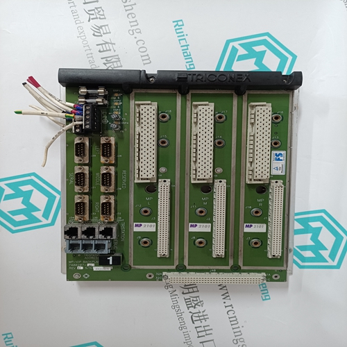
Home > Product > Gas turbine system > IS200AEPCH1BAA General electric (ge) card
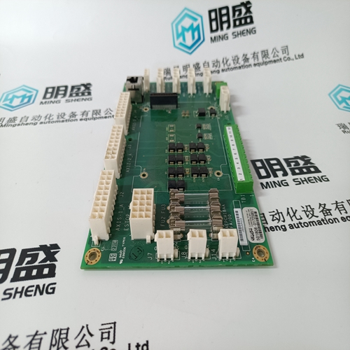
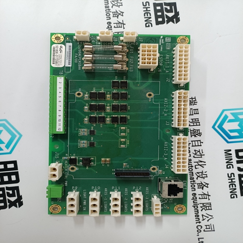
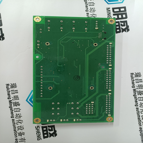
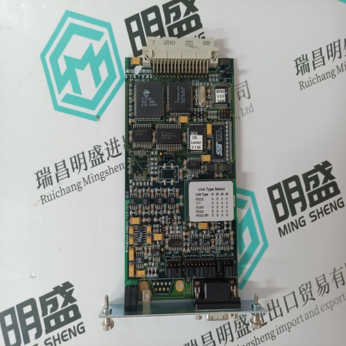
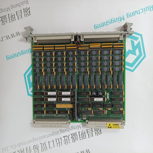
IS200AEPCH1BAA General electric (ge) card
- Product ID: IS200AEPCH1BAA
- Brand: GE
- Place of origin: the United States
- Goods status: new/used
- Delivery date: stock
- The quality assurance period: 365 days
- Phone/WhatsApp/WeChat:+86 15270269218
- Email:stodcdcs@gmail.com
- Tags:IS200AEPCH1BAAGeneral electric (ge) card
- Get the latest price:Click to consult
The main products
Spare parts spare parts, the DCS control system of PLC system and the robot system spare parts,
Brand advantage: Allen Bradley, BentlyNevada, ABB, Emerson Ovation, Honeywell DCS, Rockwell ICS Triplex, FOXBORO, Schneider PLC, GE Fanuc, Motorola, HIMA, TRICONEX, Prosoft etc. Various kinds of imported industrial parts
Products are widely used in metallurgy, petroleum, glass, aluminum manufacturing, petrochemical industry, coal mine, papermaking, printing, textile printing and dyeing, machinery, electronics, automobile manufacturing, tobacco, plastics machinery, electric power, water conservancy, water treatment/environmental protection, municipal engineering, boiler heating, energy, power transmission and distribution and so on.
IS200AEPCH1BAA General electric (ge) card
The Quad Relay Interface Card provides the interface between a Four Channel Control Card and the field wiring. An Expansion Relay Card can also be factory fitted to the Quad Relay Interface Card and the resultant assembly is then known as the Relay Interface Assembly. This assembly is used to expand the standard four relays available for alarms on the Quad Relay Interface to 16 relays.
Provides connections between the four sensors and the control card. In addition, four single pole relays provide voltage free contact outputs that can be configured for the A1 alarm level, A2 alarm level, A3 alarm level, fault or inhibit conditions and as individual alarms or master alarms. Connections for power, remote inputs and analogue outputs are also provided.
The Engineering Card is always fitted into the right-hand slot of the rack and provides:a. Routeing of the 24V dc input from the DC Input Card to the backplane of the rack. b. A backplane serial communications controller and monitor. c. A time and date reference. d. An RS232 external engineering interface.e. Depending upon the security level, the operation of the following rack facilities: Catalytic sensor head current monitoring and adjustment. Alarm set point checking, adjustment and testing. Sensor signal zero adjustment. Sensor signal span adjustment and setting of sensor life monitoring values. Sensor line monitoring. Enabling of control card alarm inhibit. Checking and adjustment of the system clock.
Expansion Relay Card
The Expansion Relay Card provides relay expansion for a Four Channel Control Card and the Quad Relay Interface Card. The Expansion Relay Card is connected to the Quad Relay Interface Card and provides 12 additional relays, eight of which are single pole changeover and four are single pole single throw. The relays can be configured for A1, A2, A3, fault or inhibit alarms and as individual or master outputs. When the Expansion Relay Card is connected to the Quad Relay Interface Card, the pair of cards take up two slots of the rack. For this reason a blank panel has to be fitted to the rack front panel adjacent to the associated Four Channel Control Card.
The Engineering Card is used on a System 57 rack to provide a common interface that enables the user to perform all the required functions to commission and operate each fitted control card. The front panel is fitted with a series of tactile push-buttons for the operation of various functions, LEDs to provide rack power and communications status and a mini DIN socket for the connection of a serial printer, computer or an engineering key. The Engineering Key is used to unlock functions that can alter the operation of a control card.
One of four optional modules
may be fitted to the Engineering Card: a. Master Alarm Update Module This facility provides an indication when a new alarm occurs on any channel in the rack, even if a previous alarm condition already exists. b. Event Printing Module This facility provides time stamped reporting of alarm and fault events as they occur and system status at predetermined regular intervals. c. Modbus Interface Module RS422/485 This facility provides for digital communication between the System 57 Control System and an external computer system using the RS422/485 serial data format and the Modbus communication protocol. d. Modbus Interface Module RS232 This facility provides for digital communication between the System 57 Control System and an external computer system using the RS232 serial data format and the Modbus communication protocol.The dc power to the rack can enter the sub-rack via the DC Input Card. This power may be supplied by the user from an external nominal 24V dc supply. The dc supply is routed through the Engineering Card and sub-rack back plane to all cards in the rack and is protected by a fuse on the DC Input Card. There is a two part terminal block, TB1, to aid removal of the card without disconnecting each of the connected wires.
