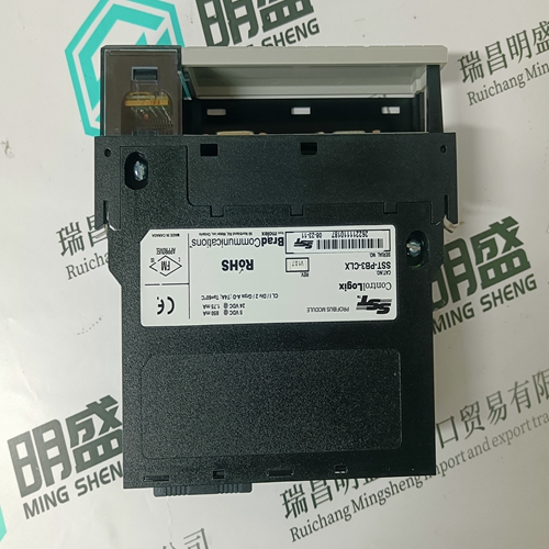
Home > Product > Gas turbine system > IS210AEBIH3BEC Gas turbine electrical module
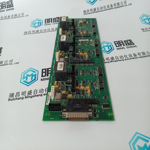
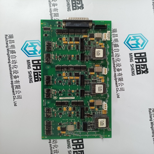
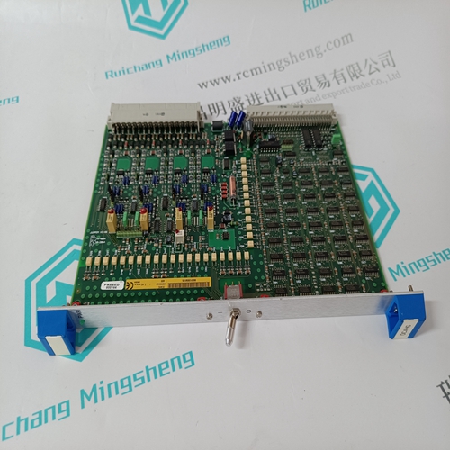
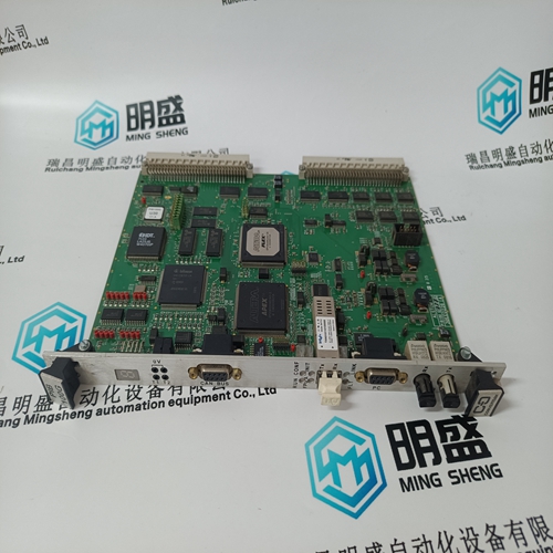
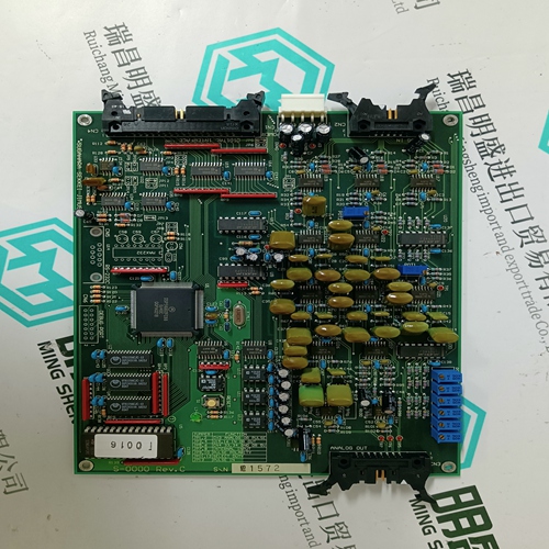
IS210AEBIH3BEC Gas turbine electrical module
- Product ID: IS210AEBIH3BEC
- Brand: GE
- Place of origin: the United States
- Goods status: new/used
- Delivery date: stock
- The quality assurance period: 365 days
- Phone/WhatsApp/WeChat:+86 15270269218
- Email:stodcdcs@gmail.com
- Tags:IS210AEBIH3BECGas turbine electrical module
- Get the latest price:Click to consult
The main products
Spare parts spare parts, the DCS control system of PLC system and the robot system spare parts,
Brand advantage: Allen Bradley, BentlyNevada, ABB, Emerson Ovation, Honeywell DCS, Rockwell ICS Triplex, FOXBORO, Schneider PLC, GE Fanuc, Motorola, HIMA, TRICONEX, Prosoft etc. Various kinds of imported industrial parts
Products are widely used in metallurgy, petroleum, glass, aluminum manufacturing, petrochemical industry, coal mine, papermaking, printing, textile printing and dyeing, machinery, electronics, automobile manufacturing, tobacco, plastics machinery, electric power, water conservancy, water treatment/environmental protection, municipal engineering, boiler heating, energy, power transmission and distribution and so on.
IS210AEBIH3BEC Gas turbine electrical module
The STEL alarm will be activated when the time weighted average concentration of a toxic gas, usually averaged over 10 or 15 minutes, crosses a preconfigured threshold. The control card alarm LED, associated during setup to the STEL alarm, will be illuminated as described in Section 2.3.1f and the message display will show STEL.
LTEL Alarm (Long Term Exposure Limit). The LTEL alarm will be activated when the time weighted average concentration of a toxic gas, usually averaged over 8 hours, crosses a preconfigured threshold. The control card alarm LED, associated during setup to the LTEL alarm, will be illuminated as described in Section 2.3.1f and the message display will show LTEL. f. Individual Alarm An individual alarm is caused by the input to an individual control channel crossing a preconfigured threshold and is not related to any other control channel. The relevant LED (A1, A2, A3, Fault, Inhibit) will illuminate on the control card with the alarm condition as described in Section 2.3.1.
Update Alarm
The update alarm facility provides a common alarm indication whenever a new alarm occurs, even if a previous alarm condition exists. The update alarm can be configured to operate on a single card or on a grouped alarm e.g. master or zoned. The update alarm is especially useful in systems configured with only master or group/zone relays, where the occurrence of subsequent alarms will not cause further relay output compared to that caused by the initial alarm. The relevant LED (A1, A2, A3, Fault, Inhibit) will illuminate on the control card with the alarm condition as described in Section 2.3.1. The ATTN LED will also illuminate as described in Section 2.3.2b and the message display will show the cause of the update alarm, e.g., -FT-, -IN-, -A1-, etc. When relays are used for signalling update alarms, no other alarms or messages must be allocated to them.A rising alarm is caused by a rising level of the parameter being measured crossing a preconfigured threshold. This will also cause the associated alarm LED to illuminate as described in Section 2.3.1.A normally energised relay is activated when the power is removed from it, (eg. in the event of a system power failure). The LEDs will illuminate when an alarm or fault condition occurs irrespective of the relay configured state.
Time Delay Alarms
The operation in response to alarm events of certain relays may be modified by applying a delay function to the relays. Time delay functions are available to delay the activation of a relay for a short period after an alarm event occurs and/or to maintain relay activation for a period after the alarm event has cleared. The time delay facilities are available for: i. Relays 1 to 4 if the Quad Relay Interface Card is fitted. ii. Relays 1 to 8 if the Relay Interface Assembly is fitted. The time delay function is useful to prevent spurious alarms and to ensure appropriate minimum operating times for external electrical apparatus connected to the relay The Four Channel Control Card provides the necessary power supplies to the associated sensors and conditions the incoming sensor signals. The received sensor signals are then processed by the microprocessor and the resultant values and any necessary alarm action, depending on the channel configuration, is carried out.
The backlit LCD provides a display of the selected sensor reading and its status, or if maintenance is being carried out on a sensor, information on the sensor set points and calibration data
