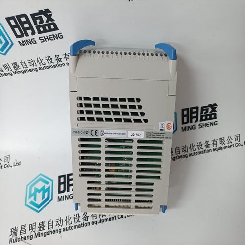
Home > Product > DCS control system > SPASI23 Industrial card
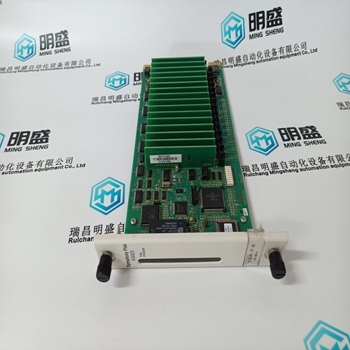
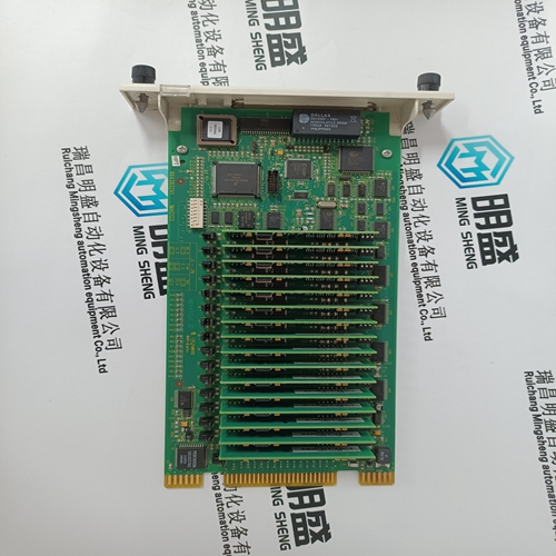
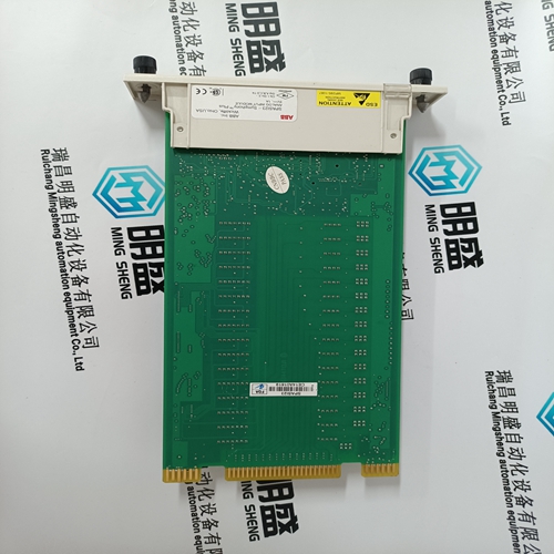
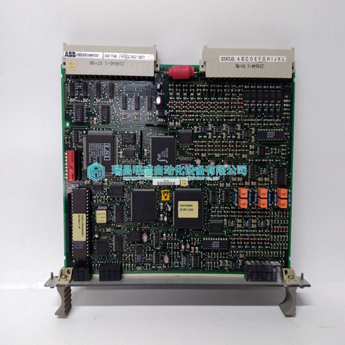
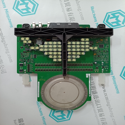
SPASI23 Industrial card
- Product ID: SPASI23
- Brand: ABB
- Place of origin: The Swiss
- Goods status: new/used
- Delivery date: stock
- The quality assurance period: 365 days
- Phone/WhatsApp/WeChat:+86 15270269218
- Email:stodcdcs@gmail.com
- Tags:SPASI23Industrial card
- Get the latest price:Click to consult
The main products
Spare parts spare parts, the DCS control system of PLC system and the robot system spare parts,
Brand advantage: Allen Bradley, BentlyNevada, ABB, Emerson Ovation, Honeywell DCS, Rockwell ICS Triplex, FOXBORO, Schneider PLC, GE Fanuc, Motorola, HIMA, TRICONEX, Prosoft etc. Various kinds of imported industrial parts
Products are widely used in metallurgy, petroleum, glass, aluminum manufacturing, petrochemical industry, coal mine, papermaking, printing, textile printing and dyeing, machinery, electronics, automobile manufacturing, tobacco, plastics machinery, electric power, water conservancy, water treatment/environmental protection, municipal engineering, boiler heating, energy, power transmission and distribution and so on.
SPASI23 Industrial card
.Zellweger Analytics Limited can take no responsibility for installation and/or use of its equipment if this is not done in accordance with the appropriate issue and/or amendment of the manual. 2. The user of this manual should ensure that it is appropriate in all details to the exact equipment to be installed and/or operated. If in doubt, the user should contact Zellweger Analytics Limited for advice. 3. The System 57 cards contain no user serviceable parts. Refer all servicing to qualified service personnel. 4. When inserting or removing system components ensure that the power is switched off. Failure to do this may result in damage to the system.
For installations in the EU, refer to EN60079-14:1997, ‘Electrical Installations in Hazardous Areas (other than mines) Additionally, the code of practice regarding Selection, installation, use and maintenance of apparatus for the detection and measurement of combustible gases or oxygen must be complied with. Refer to EN 50073. The above standards apply to the System 57 since the SENSORS may be installed in potentially hazardous atmospheres. In addition, appropriate local or national regulations shall be used.”
INSTALLATION INSTRUCTIONS
A summary of the System 57 controller installation procedures is shown below: a. Unpack and check the equipment. b. Identify a suitable location and check the cabling requirements. c. Confirm the power supply requirements. d. Install the Cabinet, 19" Mounting Frame or Panel Cutout as required. e. Fit the System 57 rack into the Cabinet, 19" Mounting Frame or Panel Cutout. f. Install the sensors and wire back to the System 57. g. Check, and if necessary reconfigure, the Four Channel Control Cards. h. Wire the sensors to the Quad Relay Interface Card terminal blocks. i. Wire the outputs from the Quad Relay Interface Card terminal blocks or from the Relay Interface Assembly if used. j. Wire the power supply to the DC Input Card. k. In individually powered applications, wire the power supply to each Quad Relay Interface Card. After installation is complete perform the commissioning procedures outlined in Chapter 5. The following sections of this chapter provide a detailed explanation of the installation operations.
LOCATION
The control system must be installed in a safe area such as a control or equipment room, away from sources of heat, with adequate ventilation and protected from the weather. There are two different System 57 rack configurations to accommodate either front or rear field wiring entry. Each configuration is available in half or full 19" width. The three most common mounting methods are: a. 19" Mounting Frame The System 57 19" 6U front and 3U rear access racks are compatible with the standard 19" (483mm) sub-rack format and may therefore be fitted into any suitable 19" mounting frame. b. Cabinet Wall mounting cabinets are available in two sizes to accommodate the 19" and half 19" 6U front access rack assemblies. c. Panel Alternatively all the racks are suitable for fitting directly into a panel cutout aperture. Power supply units are available, in both 19" and half 19" 1U formats, for applications where an ac input power source is to be used. It is recommended that the power supply units are mounted directly above the System 57 rack.
