Home > Product > Robot control system > VIBRO 200-560-000-113 VM600 Channel control card
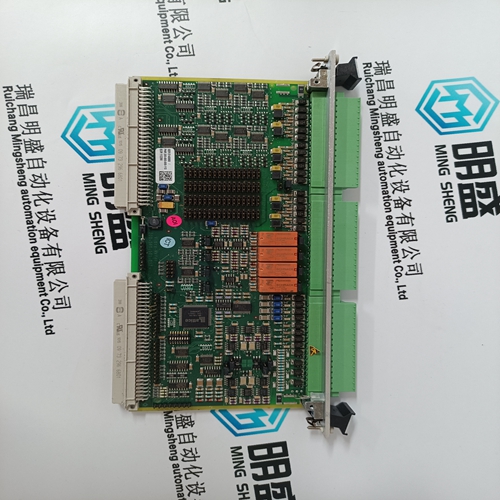
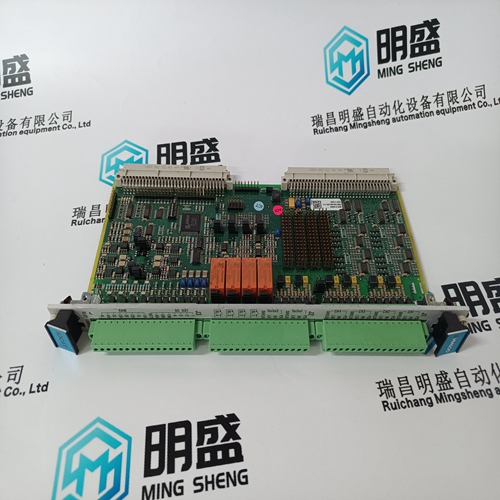
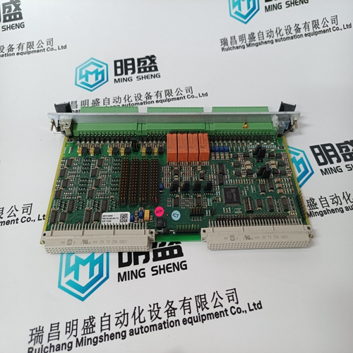
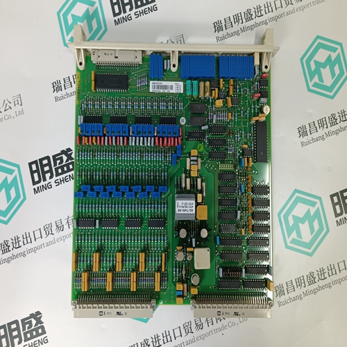
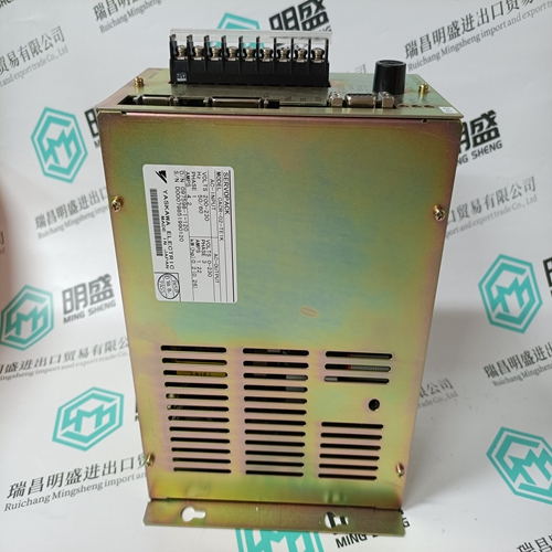
VIBRO 200-560-000-113 VM600 Channel control card
- Product ID: 200-560-000-113 VM600
- Brand: VIBRO
- Place of origin: the United States
- Goods status: new/used
- Delivery date: stock
- The quality assurance period: 365 days
- Phone/WhatsApp/WeChat:+86 15270269218
- Email:stodcdcs@gmail.com
- Tags:VIBRO200-560-000-113 VM600Channel control card
- Get the latest price:Click to consult
The main products
Spare parts spare parts, the DCS control system of PLC system and the robot system spare parts,
Brand advantage: Allen Bradley, BentlyNevada, ABB, Emerson Ovation, Honeywell DCS, Rockwell ICS Triplex, FOXBORO, Schneider PLC, GE Fanuc, Motorola, HIMA, TRICONEX, Prosoft etc. Various kinds of imported industrial parts
Products are widely used in metallurgy, petroleum, glass, aluminum manufacturing, petrochemical industry, coal mine, papermaking, printing, textile printing and dyeing, machinery, electronics, automobile manufacturing, tobacco, plastics machinery, electric power, water conservancy, water treatment/environmental protection, municipal engineering, boiler heating, energy, power transmission and distribution and so on.
VIBRO 200-560-000-113 VM600 Channel control card
The field terminals on the Quad Relay Interface and Relay Interface Assembly accept single or multi-stranded wire up to 2.5mm˝ (14 AWG). Cables should be routed carefully to avoid physical and environmental hazards such as mechanical stress and high temperatures. Sensor wiring should consist of a cable with an earthed outer shield and should be routed away from sources of interference such as ac power cables, motors, machinery etc. All sensor cabling is subject to a maximum cable length that is dependant upon the cable line resistance and sensor types. The current ratings of the power and relay cables should always be higher than the worst case maximum load requirement. All sensor field cables must be screened in order to ensure correct operation of the system and to meet European Standards for RFI and EMC. The cable screen of each sensor should be connected to a GROUND terminal at the cabinet entry or the ground terminal of the appropriate Quad Relay Interface Card or another suitable ground point.
POWER REQUIREMENTS
The System 57 operates from a nominal 24V (18V to 32V) dc power supply input which may be derived from various sources including the mains ac, via a separate ac to dc power supply unit, local plant dc supply and/or battery backup dc supply. The power supply may be applied to the System 57 backplane, via the DC Input Card, where the maximum backplane current is limited to 8A. The DC Input Card terminal blocks allow flexible power connections and diode isolation for two separate power supply inputs. Where the number of Four Channel Control Cards fitted and the type of sensors used would cause a backplane current in excess of the 8A maximum, it is necessary to connect the power supply to each individual control card via its Quad Relay Interface Card. As a general rule, individually powered cards are required where more than eight catalytic control cards are fitted. See Section 17 for connection details. The power supply rating required is dependent upon the sensor types, number of channels and configuration of the System 57. Table 1, the Power Budget Calculation Sheet, allows for a quick and easy calculation of the worst case power requirement for the system. In many cases a lower power rating can be used, however, a more detailed power budget analysis should be performed to confirm the exact requirement.
VENTILATION
The 5704 Control System provides the facility for a large number of channels in a very small space. In heavily populated racks, especially those with many catalytic input control cards or relays configured for normally energised operation, it is possible for the heat dissipation to cause a significant rise in temperature both within the rack and in an area close to the rack. As such, careful consideration must be given to thermal planning. To achieve most from the convection cooling, always ensure that the air can flow freely through the rack and power supply. Do not obstruct the air vent holes in the top and bottom of the rack and if possible space the control cards evenly within the rack. It is recommended that during commissioning the operating temperature of the rack is checked to ensure that the maximum operating temperature of 55oC is not exceeded. In some cases the addition of forced air ventilation may be required. Maximum power supply configuration allowed without provision for additional ventilation is 100w for 8 way cabinet and 200w for 16 way cabinet.