Home > Product > Servo control system > DEIF DU-2/MKIII controller
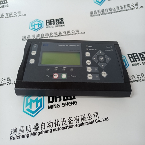
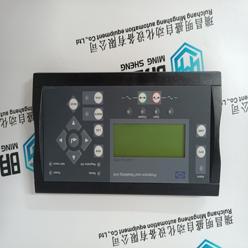
DEIF DU-2/MKIII controller
- Product ID: DU-2/MKIII
- Brand: DEIF
- Place of origin: the United States
- Goods status: new/used
- Delivery date: stock
- The quality assurance period: 365 days
- Phone/WhatsApp/WeChat:+86 15270269218
- Email:stodcdcs@gmail.com
- Tags:DEIF DU-2/MKIIIcontroller
- Get the latest price:Click to consult
The main products
Spare parts spare parts, the DCS control system of PLC system and the robot system spare parts,
Brand advantage: Allen Bradley, BentlyNevada, ABB, Emerson Ovation, Honeywell DCS, Rockwell ICS Triplex, FOXBORO, Schneider PLC, GE Fanuc, Motorola, HIMA, TRICONEX, Prosoft etc. Various kinds of imported industrial parts
Products are widely used in metallurgy, petroleum, glass, aluminum manufacturing, petrochemical industry, coal mine, papermaking, printing, textile printing and dyeing, machinery, electronics, automobile manufacturing, tobacco, plastics machinery, electric power, water conservancy, water treatment/environmental protection, municipal engineering, boiler heating, energy, power transmission and distribution and so on.
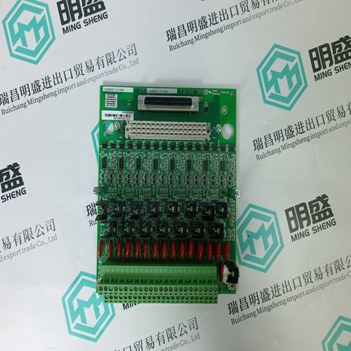
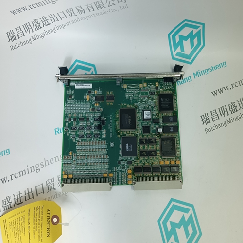
DEIF DU-2/MKIII controller
Ensure that each control card is compatible with the proposed sensor/ transmitter to be connected to that control card. Ensure that where an AC to DC Power Supply Unit is to be used, this is compatible with the local mains ac supply voltage and that the PSU power rating is adequate for its individual system load. Note: The model 05701-A-0405 and 05701-A-0406 AC to DC Power Supply Units operate, without the requirement of input voltage adjustments, from an 85V to 264V, 47Hz to 440Hz ac supply inputs.
Insert the rack into the aperture and secure using M6, or similar bolts, through the four mounting holes located upon the front flange plates.Ensure adequate support at the rear of rear access racks.Prepare and connect the cable ends to Quad Relay Interface and Expansion Relay Cards terminals. For terminal identification see Chapter 2. Where possible keep sensor cables separate from the other wiring.Ensure that the rack is properly earthed by connecting a suitable earth cable to the earth stud located at the rear of the rack.
CABINET INSTALLATION
Two cabinets are available, an 8-way to accommodate the 8-way front access rack and a 16-way to accommodate the 16-way front access rack. The cabinet must be secured to a wall, or other suitable vertical surface, as follows: (1) Knock out the bottom gland-plate entries as appropriate for the system cabling and fit the glands before mounting the cabinet. (2) Attach the four mounting brackets provided to the cabinet. (3) Using the dimensions shown mark the position of the mounting holes on the mounting surface. (4) Drill and wall plug the mounting holes as necessary. Note: The mounting brackets will accept up to a 10mm ( 0.4'' ) diameter screw. (5) Secure the cabinet in position using appropriate mounting screws. (6) Fit the System 57 Rack and AC to DC Power Supply Unit (if required) into the cabinet in the positions as shown: (7) Pass cables through the gland adjacent to field terminal blocks, where possible keeping the sensor cable(s) separate from the other wiring. (8) Prepare and connect the cable ends to Quad Relay Interface and Expansion Relay Card terminals. For terminal identification see Chapter 2. (9) Ensure that the cabinet is properly earthed by connecting a suitable earth cable to the earth stud located in the bottom panel of the cabinet. (10) Close and lock the cabinet.
SENSOR INSTALLATION
Always install the sensors in accordance with the Sensor Operating Instructions. In general, sensors for lighter than air gasses should be located at a high level and sensors for heavier than air gasses should be located at a low level. Do not install the sensors: a. Where the normal air flow may be impeded. b. In corners of rooms where static air pockets may exist. c. Near sources of heat such as convector heaters. Do install the sensors: a. As close as possible to the potential source of gas to be detected in order to give the maximum possible warning. b. So that they are accessible for maintenance work.Sensors should be located such that the line resistance of cable does not exceed the maximum permitted. The table below gives a quick guide to the maximum cable lengths permitted for specific sensors, when connected by stranded copper conductor cables of various sizes to a System 57 running at the minimum dc input voltage.The figures in the table above provide a useful reference guide to maximum cable lengths, however, in many circumstances longer cable runs can be used. eg. Where the dc input voltage is higher than the minimum. In these circumstances a more detailed analysis is required to determine maximum line resistance. WARNING It is required that verification by testing that cable faults (open circuit and short circuit) at the transmitter’s side are correctly detected by the control card. The control card shall indicate ER81, ER87 or ER88 in this case.