Home > Product > PLC programmable module > PROSOFT 6104-WA-PDPM Communication module
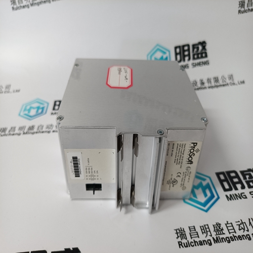
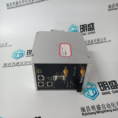
PROSOFT 6104-WA-PDPM Communication module
- Product ID: 6104-WA-PDPM
- Brand: PROSOFT
- Place of origin: the United States
- Goods status: new/used
- Delivery date: stock
- The quality assurance period: 365 days
- Phone/WhatsApp/WeChat:+86 15270269218
- Email:stodcdcs@gmail.com
- Tags:PROSOFT6104-WA-PDPMCommunication module
- Get the latest price:Click to consult
The main products
Spare parts spare parts, the DCS control system of PLC system and the robot system spare parts,
Brand advantage: Allen Bradley, BentlyNevada, ABB, Emerson Ovation, Honeywell DCS, Rockwell ICS Triplex, FOXBORO, Schneider PLC, GE Fanuc, Motorola, HIMA, TRICONEX, Prosoft etc. Various kinds of imported industrial parts
Products are widely used in metallurgy, petroleum, glass, aluminum manufacturing, petrochemical industry, coal mine, papermaking, printing, textile printing and dyeing, machinery, electronics, automobile manufacturing, tobacco, plastics machinery, electric power, water conservancy, water treatment/environmental protection, municipal engineering, boiler heating, energy, power transmission and distribution and so on.
PROSOFT 6104-WA-PDPM Communication module
Hardware - Actuator Outputs This control provides an isolated group of (2) Actuator outputs for customer use. Each driver can be configured for low-range (20 mA) or high-range (200 mA) operation. Fault monitoring of individual source and return currents is included. Features (2) Actuator Output channels (4-20 mA, 20-200 mA) Source and return current monitoring Group isolated from other circuits Capable of driving higher impedance loads Woodward GAP block, diagnostics, and configuration support GAP configurable update rates of 5 ms to 160 ms
This control provides an isolated group of (20) discrete input channels for use with +24 V (dc) signals. An isolated Contact Power voltage supply of +24 V (dc) is provided to use with the discrete inputs. This supply includes short-circuit and over-voltage protection. Features (20) Discrete Input Channels for +24 V (dc) signals +24 V Contact Power with short-circuit and diode protection Isolated power and discrete input group Woodward GAP block, diagnostics, and configuration support GAP configurable update rates of 5 ms to 160 ms Time-stamping capability (1 ms)
Hardware - Relay Outputs
This control provides (8) Isolated, Form-C Relay outputs with NO, COM, NC contacts available at the terminal block. Features (8) Relay Output Channels Each Relay Output provides NO, COM, and NC contacts Each Relay Output channel provides a coil voltage readback fault Woodward GAP block, diagnostics, and configuration support Contact isolation maintained at terminal blocks ATEX approved version available using hermetically sealed relays GAP configurable update rates of 5 ms to 160 ms
The CPU board runs diagnostics that display troubleshooting messages through the debug Service Port and AppManager. Additional information on diagnostics tests, subsequent LED flash codes, and serial port messages is contained in the VxWorks manual.
Power checks Verify proper polarity on power connections Verify power source and wire size is sufficient for all loads Verify input power voltage is correct (i.e.: low voltage unit is 18 V to 36 Vdc) Verify PS(+) and PS(–) impedance to EARTH is > 10 MΩ
Turbine Start Modes
The 505 has three turbine start modes (manual, semi-automatic or automatic) from which to choose from. One of these start modes must be chosen and programmed to perform a system start-up. Once a ‘RUN’ command is issued, the speed set point and valve limiter are manipulated automatically by the 505 or manually by the operator, depending on which start mode is selected. After a turbine start sequenced has been completed, turbine speed will be controlled at a minimum controlling speed. The minimum controlling speed may be idle if idle/rated is being used, low idle if the auto start sequence is used, or minimum governor if neither idle/rated or auto start sequence is used. A ‘RUN’ command may be issued from the 505 keypad, an external contact, or through Modbus communications. If an ‘External Run’ contact is programmed, a ‘RUN’ command is issued when the contact is closed. If the contact is closed prior to start-up it must be opened and re-closed to issue a ‘RUN’ command. If turbine speed is sensed when a ‘RUN’ command is issued, the control will instantly match the speed set point to the sensed speed and continue towards the minimum controlling speed. In the event the sensed turbine speed is greater than the minimum controlling speed setting, the speed set point will match this sensed speed, the Speed PID will control at this point, and the control will wait for further action to be taken by the operator (unless auto start sequence is configured). If turbine speed is first sensed within a critical speed avoidance band when a ‘Run’ command is received, the speed set point will match the actual speed, decrease to the lower end of the critical avoidance band, and wait for action to be taken by the operator.
