Home > Product > Gas turbine system > IS200STAOH2AAA control module
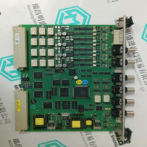
IS200STAOH2AAA control module
- Product ID: IS200STAOH2AAA
- Brand: GE
- Place of origin: the United States
- Goods status: new/used
- Delivery date: stock
- The quality assurance period: 365 days
- Phone/WhatsApp/WeChat:+86 15270269218
- Email:stodcdcs@gmail.com
- Tags:IS200STAOH2AAAcontrol module
- Get the latest price:Click to consult
The main products
Spare parts spare parts, the DCS control system of PLC system and the robot system spare parts,
Brand advantage: Allen Bradley, BentlyNevada, ABB, Emerson Ovation, Honeywell DCS, Rockwell ICS Triplex, FOXBORO, Schneider PLC, GE Fanuc, Motorola, HIMA, TRICONEX, Prosoft etc. Various kinds of imported industrial parts
IS200STAOH2AAA control module
The dimensions of the standard braking choppers and braking resistors to be installed outside the ACS 600 housing are given in the following pages. The dimensions are in millimetres.
The Maximum Braking Power (PBRmax) for each standard ACS 600/braking chopper combination is given in Table 2-1 and Table 2-2 in Chapter 2 – Overview. The rated value is specified for a reference braking cycle (ten minute braking cycle: one minute braking, nine minutes at rest). If the actual braking cycle does not correspond to the reference cycle, the maximum allowed braking power must be calculated. 1. Braking energy transferred during any ten minute period must be less than or equal to the energy transferred during the reference braking cycle.
Duration of a braking cycle is 30 minutes. The braking time is 15 minutes. Result: If the braking time exceeds ten minutes the braking is considered continuous. The allowed continuous braking power is ten percent of the Maximum Braking Power (PBRmax).
Result:
The maximum allowed braking power for the cycle is 37 % of the rated value given for the reference cycle. Example 3 Duration of a braking cycle is three minutes. The braking time is 10 seconds.Result: The maximum allowed braking power for the cycle is equal to the Maximum Braking Power (PBRmax) given for the reference cycle.
50 W internal power supply with redundant inputs and 50 ms full rack power fail protection and internal safe-shutdown UPS Supporting direct battery and/or UPS supply Input level: 24 V, +50 %, -25 % (18 to 36 V) Safety Input (IN): High: 9 to 36 V or -9 to -36 V with reference to common Low: 5 to -5 V with reference to common Impedance: Approximately 4 kΩ Isolation: Optically isolated from other potentials, 550 V 50 Hz Output (OUT): Digital relay output, 24 V, maximum 1 A resistive Interfaces 1 x EtherCAT® OUT (Port 2), electrical: 100Base-TX, 8P8C (“RJ45”), shielded Cat 5, >0.76 µm gold plating 1 x EtherCAT® OUT (Port 1), optical: 100Base-FX, SC connectors, multimode fibre 62.5 µm, OM1 1 x Ethernet port (Ethernet): 100Base-TX, 8P8C (“RJ45”), shielded Cat 5, >0.76 µm gold plating 1 x RS-422 port: ANSI/TIA/EIA-422-B: 4.8 to 460.8 kbit/s (full duplex) Service USB 2.0, console on virtual COM port, 115.2 kbit/s (8/N/1), no flow control Processor 333 MHz industrial grade 32 bit PowerQUICC II Pro CPU supporting 1 ms control loop Operating system Embedded real-time DEIF OS based on Linux. Fail-safe remote OS and I/O firmware update. Power fail-safe, self-monitoring and error-correcting file system. Start-up time: <10 s (from power on to customer application start-up). PLC run-time CODESYS version 3 (optional)