Home > Product > Servo control system > B&R 8AC120.60-1 Servo drive card
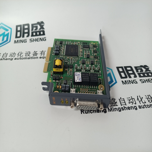
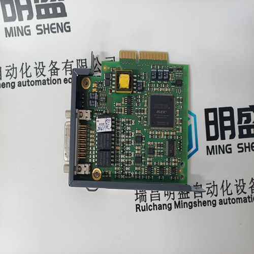

B&R 8AC120.60-1 Servo drive card
- Product ID: 8AC120.60-1
- Brand: B&R
- Place of origin: the United States
- Goods status: new/used
- Delivery date: stock
- The quality assurance period: 365 days
- Phone/WhatsApp/WeChat:+86 15270269218
- Email:stodcdcs@gmail.com
- Tags:B&R8AC120.60-1Servo drive card
- Get the latest price:Click to consult
The main products
Spare parts spare parts, the DCS control system of PLC system and the robot system spare parts,
Brand advantage: Allen Bradley, BentlyNevada, ABB, Emerson Ovation, Honeywell DCS, Rockwell ICS Triplex, FOXBORO, Schneider PLC, GE Fanuc, Motorola, HIMA, TRICONEX, Prosoft etc. Various kinds of imported industrial parts
Products are widely used in metallurgy, petroleum, glass, aluminum manufacturing, petrochemical industry, coal mine, papermaking, printing, textile printing and dyeing, machinery, electronics, automobile manufacturing, tobacco, plastics machinery, electric power, water conservancy, water treatment/environmental protection, municipal engineering, boiler heating, energy, power transmission and distribution and so on.
B&R 8AC120.60-1 Servo drive card
When using the second temperature analog input an option to use the temperature difference, as a condition for a Warm or Hot start, is also available. Select the “Use Temperature Difference” checkbox in the Turbine Start configuration menu. The difference between Start Temperature 1 and 2 must be less than the configured amount for Hot/Warm conditions to be met. If the “Select Hot/Cold” contact input is configured, the Hot/Cold Temperature logic will respond to this signal. If the contact is open, Cold will be selected. If the contact is closed, it allows for a Warm or Hot start if all the temperature conditions for the Warm or Hot start are satisfied. When a temperature input fails then the Hot/Warm conditions for that input will not be met, which means that the start sequence will use the Cold start values. The start will proceed normally as if the turbine is running the cold condition.
The ‘Hold Time’ is only used if the speed setpoint exactly equals the associated Idle hold setpoint. If the speed setpoint is different from this hold point, selecting ‘Continue’ will ramp the setpoint up to the next hold point regardless of the ‘Hold Time’. Caution should be taken when raising or lowering the speed set point to ‘Halt’ the Automatic Start Sequence.
Halting the Auto Start Sequence
The Auto Start Sequence can be halted at any time from the 505 keypad, contact input or through Modbus. The sequence can be halted by a halt command, a raise or lower speed set point command, or when a speed set point is directly ‘Entered’ from the 505 keypad or through Modbus communications. When the sequence is halted, the delay timers do not stop if they have already started counting down. The sequence will resume when a ‘Continue’ command is issued. If there were 15 minutes remaining to hold at an idle speed and the Halt command was issued for 10 minutes before a issuing a Continue command, the sequence would remain at the idle speed for the remainder of the ‘Hold Time’— which in this example is 5 minutes.
The halting and continuing of the Auto Start Sequence can be performed through the 505 keypad, contact input, or Modbus. The last command given from any of these three sources determines the mode of operation. However, a shutdown condition will disable this function, requiring it to be re-enabled after a start-up has been performed. If a 505 contact input is programmed to function as a Halt/Continue command, the sequence is halted when the contact is open, and continued when the contact is closed. The Halt contact can be either open or closed when a Reset command is given. If the contact is closed, it must be opened to allow the sequence to be halted. If the contact is open, it must be closed and reopened to issue a halt command. Alternatively, a relay can be programmed to indicate when the Auto Start Sequence is halted.
Single/Split-Range Actuators
An option is available to automatically halt the auto start sequence at the idle set points. This feature would result in the unit automatically stopping or halting at the low idle set point and at the high idle set point. If the unit is started and the speed is above the low idle set point, the sequence will initialize as halted. The sequence must be given a ‘Continue’ command once halted. The hold timers are still active with this option. If ‘Continue’ is selected and the hold timer has not expired, the sequence will remain in a timed wait until the hold timer has expired and then continue from that point. When the ‘Auto Halt at Idle Setpts’ option is programmed, the Auto Start Sequence Continue contact input only requires a momentary closure to continue the sequence. Automatic Start Sequence Idle Temperatures In addition to the Automatic Start Sequence Idle delay timers and “Auto Halt at Idle Setpoints” features, temperature analog inputs can be used to determine when the start sequence may continue from an Idle setpoint. These inputs will allow for a temperature permissive to be configured for each idle speed level. The start sequence will not continue from that idle until the temperature permissive is met.