Home > Product > Robot control system > BRAKE BCC-1 Brake control card

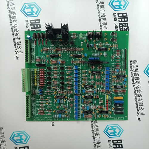
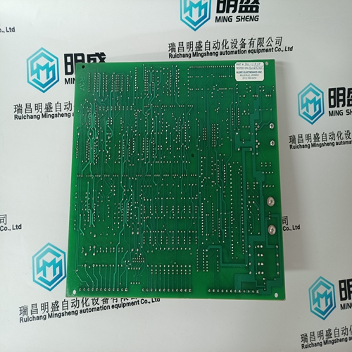
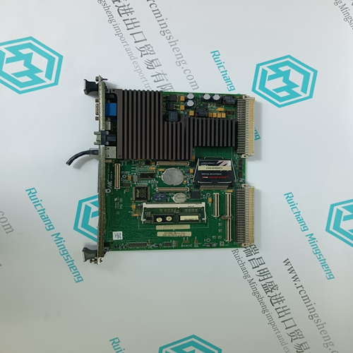
BRAKE BCC-1 Brake control card
- Product ID: BCC-1
- Brand: BRAKE
- Place of origin: the United States
- Goods status: new/used
- Delivery date: stock
- The quality assurance period: 365 days
- Phone/WhatsApp/WeChat:+86 15270269218
- Email:stodcdcs@gmail.com
- Tags:BRAKEBCC-1Brake control card
- Get the latest price:Click to consult
The main products
Spare parts spare parts, the DCS control system of PLC system and the robot system spare parts,
Brand advantage: Allen Bradley, BentlyNevada, ABB, Emerson Ovation, Honeywell DCS, Rockwell ICS Triplex, FOXBORO, Schneider PLC, GE Fanuc, Motorola, HIMA, TRICONEX, Prosoft etc. Various kinds of imported industrial parts
Products are widely used in metallurgy, petroleum, glass, aluminum manufacturing, petrochemical industry, coal mine, papermaking, printing, textile printing and dyeing, machinery, electronics, automobile manufacturing, tobacco, plastics machinery, electric power, water conservancy, water treatment/environmental protection, municipal engineering, boiler heating, energy, power transmission and distribution and so on.
BRAKE BCC-1 Brake control card
If “Use Temperature for Autostart” is configured, the start sequence will determine if the “Start Temperature 1” analog input is greater than the configured “Temperature 1 Setpoint” for each Idle speed. If so, the start sequence will continue as long all other permissives are met, which include the idle timer and any halt command. A second temperature analog input can be used with the Automatic Start Sequence temperature feature as well. This requires configuring a second analog input as “Start Temperature 2” and the “Use Temperature Input 2” checkbox should be selected in the Turbine Start configuration menu under “Autostart Sequence Settings”. If this option is programmed it will be use in one of the following ways - 1) It will provide a second unique setpoint relative to this temperature input for each idle speed level configured. For the unit to advance from one Idle speed to the next, both temperature conditions must be met. 2) Using the second temperature analog input makes available an option to use the temperature difference between these 2 signals. Select the “Use Temperature Difference” checkbox in the Turbine Start configuration menu under “Autostart Sequence Settings”. For the unit to advance from one Idle speed to the next, the difference between Start Temperature 1 and 2 must be less than the configured amount, in addition to the individual temperature setpoints.
Speed Control Overview
The speed control receives a turbine speed signal from one or two magnetic pickups or proximity probes. The ‘MPU Gear Ratio’ and the ‘Teeth Seen By MPU’ settings are configured to allow the 505 to calculate actual turbine speed. The control will always use the highest speed signal received as the validated turbine speed process variable. The Speed PID (proportional, integral, derivative control amplifier) then compares this signal to the set point to generate an output signal to the governor valve actuator (through a low signal select bus). The speed control’s set point is adjustable with raise or lower commands, through the 505 keypad, remote contact inputs or the communication line. This set point can also be directly set by entering a new set point through the 505 keypad or via Modbus/OCP. In addition, an analog input can be programmed to remotely position the speed set point
If configured, the following conditions must be met to continue from each idle speed: “Auto Halt at Idle Setpoints” not selected or operator ‘Continue’ command. Idle delay time expired. Start Temperature 1 is greater than “Temperature 1 Setpoint”. Start Temperature 2 is greater than “Temperature 2 Setpoint”. Difference between Start Temperature 1 and 2 is less than “Max Temperature Difference”.
Speed PID Operational Modes
The Speed PID operates in one of the following modes, depending on configuration and system conditions: 1. Speed Control 2. Frequency Control 3. Unit Load Control (droop) Turbine inlet valve position (505 LSS position) control Generator Load control
When not programmed for generator applications, the 505 Speed PID operates in a Speed control mode at all times. When programmed for generator applications, the state of the generator and utility tie breakers determine the operational mode of the Speed PID. When the Generator breaker contact is open, the Speed PID operates in a Speed control mode. When the generator breaker is closed and the utility tie breaker is open, the Frequency control mode is selected. When both the generator and utility tie breakers are closed, a Unit Load control mode is selected.