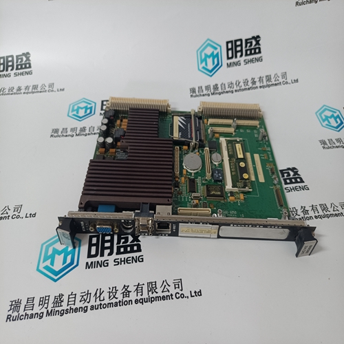
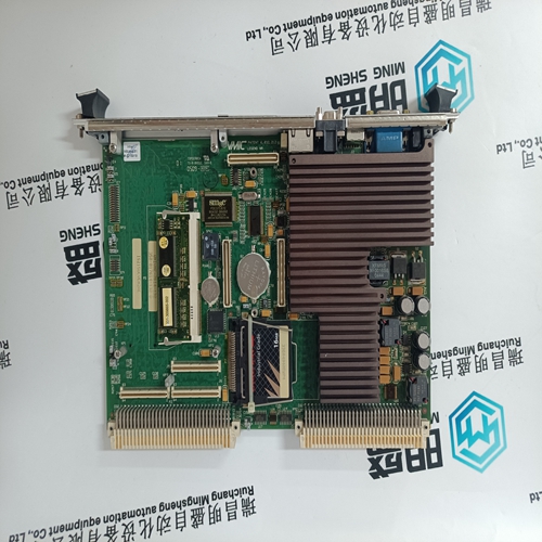
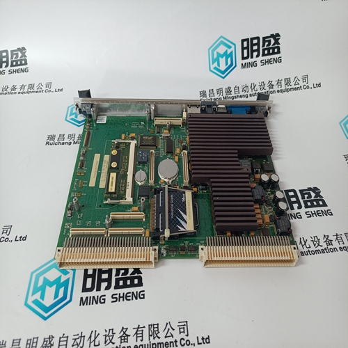
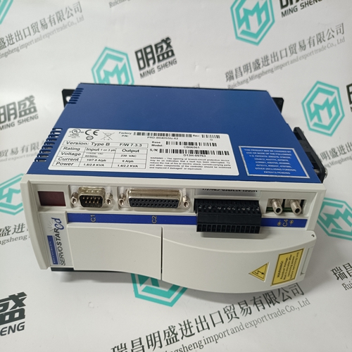
Home > Product > Gas turbine system > IS215UCVEM08B IS215UCVEH2AE combustion engine card
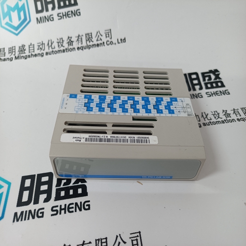
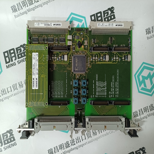
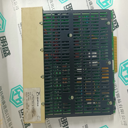
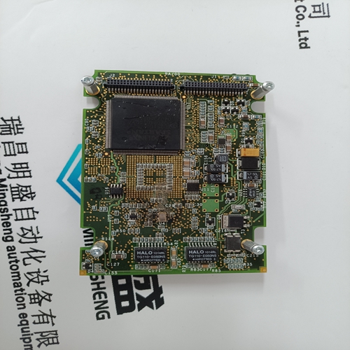
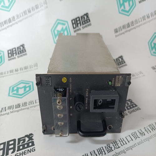
IS215UCVEM08B IS215UCVEH2AE combustion engine card
- Product ID: IS215UCVEM08B IS215UCVEH2AE
- Brand: GE
- Place of origin: the United States
- Goods status: new/used
- Delivery date: stock
- The quality assurance period: 365 days
- Phone/WhatsApp/WeChat:+86 15270269218
- Email:stodcdcs@gmail.com
- Tags:IS215UCVEM08B IS215UCVEH2AEcombustion engine card
- Get the latest price:Click to consult
The main products
Spare parts spare parts, the DCS control system of PLC system and the robot system spare parts,
Brand advantage: Allen Bradley, BentlyNevada, ABB, Emerson Ovation, Honeywell DCS, Rockwell ICS Triplex, FOXBORO, Schneider PLC, GE Fanuc, Motorola, HIMA, TRICONEX, Prosoft etc. Various kinds of imported industrial parts
Products are widely used in metallurgy, petroleum, glass, aluminum manufacturing, petrochemical industry, coal mine, papermaking, printing, textile printing and dyeing, machinery, electronics, automobile manufacturing, tobacco, plastics machinery, electric power, water conservancy, water treatment/environmental protection, municipal engineering, boiler heating, energy, power transmission and distribution and so on.
IS215UCVEM08B IS215UCVEH2AE combustion engine card
While in the Speed Control mode, the Speed PID will control a turbine at the same speed or frequency regardless of the load it is supplying (up to the unit’s load capability). With this configuration, no form of droop or second controlling parameter (bias logic) is used by the PID for stability or control. The following Speed PID mode descriptions are based on the 505 program’s default settings. For information on how to change the 505’s defaulted breaker logic, refer to Volume 2 of this manual. All pertinent speed control parameters are available through Modbus communications. See Chapter 6 for a list of all Modbus parameters.
Because the 505’s Speed PID and set point are used to control turbine speed and a second parameter, this second parameter (unit load) is normalized to allow all three terms (speed, set point, unit load) to be summed together within the PID summing junction. This normalization is based on a percentage of rated speed and creates a direct relationship between unit load and the Speed PID’s set point. Once unit load (0–100%) is represented as a percent of rated speed, the speed set point can be varied by this percent, above rated speed, to increase load from 0–100% when paralleled to the utility
Frequency Control
The following Frequency Control mode descriptions are based on the 505 program’s default settings. For information on how to change the 505’s defaulted breaker logic, refer to Volume 2 of this manual. The Speed PID operates in the Frequency control mode when the generator breaker is closed and the utility tie breaker is open. In the Frequency control mode, the unit will operate at the same speed or frequency regardless of the load it is supplying (up to the unit’s load capability). Refer to Figure 3-8. When breaker positions result in the Speed PID switching to Frequency control, the speed set point is instantly stepped to the last turbine speed (frequency) sensed before Frequency control was selected. This allows a bumpless transfer between modes. If the last speed sensed was not at the ‘Rated Speed Set Point’ (synchronous speed) setting, the speed set point will ramp to the ‘Rated Speed Set point’ setting at a defaulted rate of 1 rpm/s (tunable through the Service mode). In the Frequency control mode the speed set point can be varied with the Speed Set Point Raise/Lower commands, as desired, to allow manual synchronization across a tie breaker to an infinite bus. See the Synchronization section in this Chapter. For indication purposes, a relay can be programmed to energize when the unit is in Frequency control.
Unit Load Control
The 505’s Speed PID can control two independent parameters when the generator breaker is closed; frequency when the generator is isolated, and unit load when the generator is paralleled with an infinite bus. When the generator breaker and utility tie breaker inputs are both closed, the Speed PID operates in a Unit Load mode. This method of allowing a PID to control a second parameter is referred to as Droop. Giving the Speed PID two parameters to control allows it to control unit load and act as a stabilizing effect for any change in bus frequency. With this configuration, when bus frequency decreases or increases, unit load increases and decreases respectively, based on the unit’s droop setting. The net effect is a more stable bus. See Figure 3-9 for a frequency and load relationship diagram.
The term “droop” was derived from an isolated unit’s speed reaction to an increase in load when another parameter (unit load) is fed back to a Speed PID’s summing junction. The Droop term, as used throughout this manual refers to a PID’s second controlling parameter. A second parameter representing unit load is fed back into the 505’s Speed PID to allow it to control two parameters; speed when operating in an isolated mode, and unit load when paralleled to an infinite bus. See Figure 3-9.
