Home > Product > Gas turbine system > VMIVME-7614-132 350-017614-132 D combustion engine card
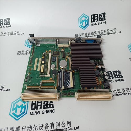

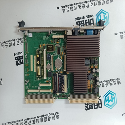
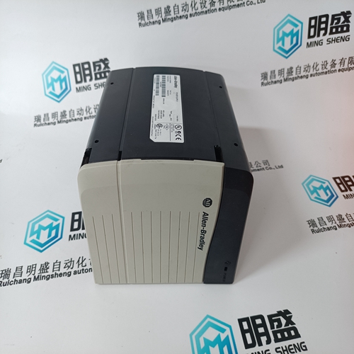
VMIVME-7614-132 350-017614-132 D combustion engine card
- Product ID: VMIVME-7614-132 350-017614-132 D
- Brand: GE
- Place of origin: the United States
- Goods status: new/used
- Delivery date: stock
- The quality assurance period: 365 days
- Phone/WhatsApp/WeChat:+86 15270269218
- Email:stodcdcs@gmail.com
- Tags:VMIVME-7614-132350-017614-132 Dcombustion engine card
- Get the latest price:Click to consult
The main products
Spare parts spare parts, the DCS control system of PLC system and the robot system spare parts,
Brand advantage: Allen Bradley, BentlyNevada, ABB, Emerson Ovation, Honeywell DCS, Rockwell ICS Triplex, FOXBORO, Schneider PLC, GE Fanuc, Motorola, HIMA, TRICONEX, Prosoft etc. Various kinds of imported industrial parts
Products are widely used in metallurgy, petroleum, glass, aluminum manufacturing, petrochemical industry, coal mine, papermaking, printing, textile printing and dyeing, machinery, electronics, automobile manufacturing, tobacco, plastics machinery, electric power, water conservancy, water treatment/environmental protection, municipal engineering, boiler heating, energy, power transmission and distribution and so on.
VMIVME-7614-132 350-017614-132 D combustion engine card
Droop feedback allows the Speed PID to control unit load (generator power or turbine valve position) once it is paralleled with a utility bus or other generating systems which do not have droop or load sharing capability. When a turbine generator set is paralleled with a utility bus, the utility determines the unit frequency/speed, thus the governor must control another parameter. The 505 uses turbine inlet valve position (LSS bus position) or generator load as a second parameter to control when paralleled to an infinite bus. The generator load or turbine inlet valve position droop percentage cannot be set greater that 10%, and is typically set to 5%. Optionally, the set droop percentage value can be changed from front panel, while turbine is running, or via a remote 4–20 mA signal (remote droop), to change the control’s response to grid frequency changes. In some extreme cases, where the utility grid frequency is unstable, and changes significantly (day/night), it is possible to change the unit’s: Frequency set point (50 Hz/60 Hz ±2.5 Hz) via front panel Frequency dead-band (±3 Hz). Used to reduce/prevent constant valve corrections due to a constantly changing grid frequency.
To configure the 505 for generator load control
when paralleled to a infinite bus, check the ‘Use KW Droop’ option on the Operating Parameters page of the configuration menu. the 505 must also be configured to accept a KW Load signal either from an analog input from a Watt transducer sensing generator load, or from a Woodward Power Management product/device via a digital communication link (Woodward Links). To configure the 505 for turbine valve position control when paralleled to an infinite bus, uncheck the ‘Use KW Droop’ option . The generator load or turbine inlet valve position droop percentage cannot be set greater that 10%, and is typically set to 5%. If the 505 is programmed to control unit load using turbine inlet valve position droop (LSS bus position), the 505 calculates load based on the valve position at the time the generator breaker was closed. This valve position is considered to be zero load. In a typical application where turbine inlet and exhaust pressures are at rated levels when the generator breaker is closed, this type of calculation allows unit load to be accurately sensed, and controlled.
Speed Set Point
The Speed PID’s set point may be adjusted from the 505 keypad, external contacts, Modbus/OPC commands, or through a 4–20 mA analog input. A specific set point setting can also be directly entered through the 505 keypad or Modbus communications. The Cascade PID also directly controls this set point when it is used. The Speed PID’s set point may be adjusted from the 505 keypad, external contacts, or through Modbus. It can be directly entered to a specific value from the 505 keypad or through Modbus commands. It can be remotely set by the Remote Speed Set Point analog input or it can be manipulated by the Cascade controller to control the Cascade input parameter. The speed set point range must be defined in the program mode. Program settings ‘Min Governor Speed Set Point’ and ‘Max Governor Speed Set Point’ define the normal operating speed range of the turbine. The speed set point cannot be raised above ‘Max Governor Speed Set Point’ setting unless an Overspeed Test is being performed. Once the speed set point is taken above the ‘Min Governor Speed Set Point’ setting, it cannot be varied below this setting again unless the Idle/Rated ramp-to-Idle command is selected or a Controlled Stop is selected.
If turbine inlet or exhaust pressures are not at rated when the breaker closes, it is recommended that the user do the following: Use the available tunable in Service mode to correct the valve position at zero load once the system is operating at rated steam pressure. To do this, adjust the Zero Load Value, (under the Service mode’s ‘BREAKER LOGIC’ header) and set this value to the correct valve position demand at Sync no load condition