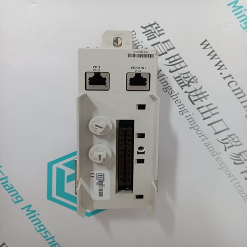
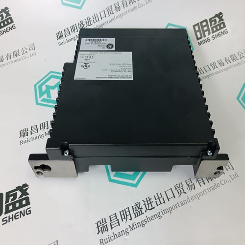
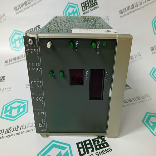
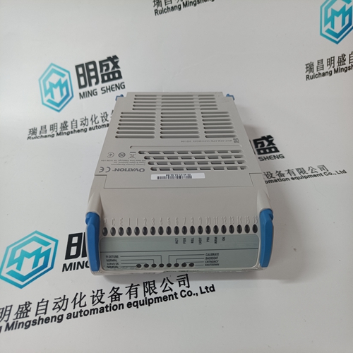
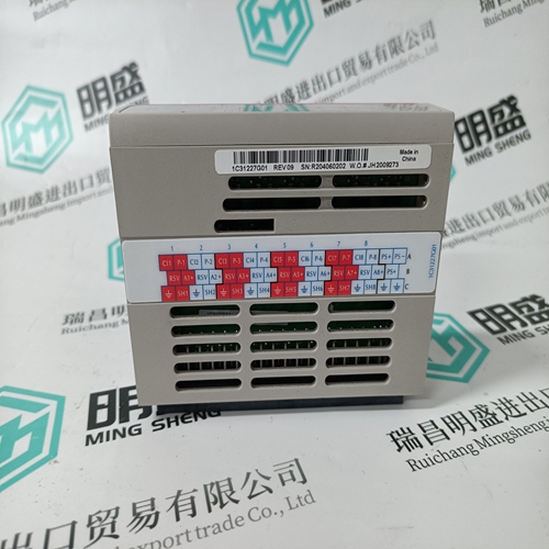
Home > Product > Robot control system > RAMIX PMC008A 700502 connector module
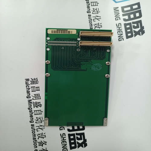
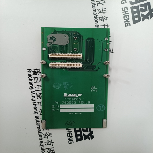
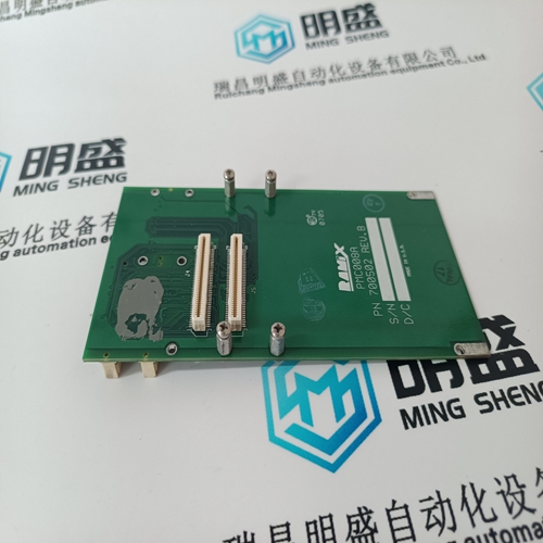
RAMIX PMC008A 700502 connector module
- Product ID: PMC008A 700502
- Brand: RAMIX
- Place of origin: the United States
- Goods status: new/used
- Delivery date: stock
- The quality assurance period: 365 days
- Phone/WhatsApp/WeChat:+86 15270269218
- Email:stodcdcs@gmail.com
- Tags:RAMIXPMC008A 700502connector module
- Get the latest price:Click to consult
The main products
Spare parts spare parts, the DCS control system of PLC system and the robot system spare parts,
Brand advantage: Allen Bradley, BentlyNevada, ABB, Emerson Ovation, Honeywell DCS, Rockwell ICS Triplex, FOXBORO, Schneider PLC, GE Fanuc, Motorola, HIMA, TRICONEX, Prosoft etc. Various kinds of imported industrial parts
Products are widely used in metallurgy, petroleum, glass, aluminum manufacturing, petrochemical industry, coal mine, papermaking, printing, textile printing and dyeing, machinery, electronics, automobile manufacturing, tobacco, plastics machinery, electric power, water conservancy, water treatment/environmental protection, municipal engineering, boiler heating, energy, power transmission and distribution and so on.
RAMIX PMC008A 700502 connector module
When not configured for a generator application, the 505 will transfer from offline to on-line dynamics once minimum governor speed is reached. Optionally a contact input may be programmed to perform a “Select On-Line Dynamics” function. If this contact is programmed the utility tie and generator breaker positions (gen applications), and the minimum speed setting status (nongen applications) do not effect dynamics selection. When the programmed contact input is open, off-line dynamics are selected and used by the Speed PID. When the programmed contact input is closed, on-line dynamics are selected and used by the Speed PID. A relay can be programmed to indicate that the On-Line Dynamics are selected and used by the Speed PID.
Dynamic gain values for the speed PID are initially defined in the configure mode and tunable at any time. For Off-Line settings there is 1 set of values for the Proportional, Integral and Derivative terms. The On-Line settings can be a single set of values or a curve created by optimizing the dynamics at 2 or 3 different load points. The procedure for setting these values is as follows. 1. Start by manually setting the gains for both Off-Line and On-Line conditions, referring to the PID Dynamic Adjustments section in this manual for completing this process. 2. Use the automated PID Dynamic Optimizer routine that will automatically analyze the system response and calculate ideal gains for that particular running condition.
Remote Speed Set Point
The Speed set point can be positioned remotely through an analog signal by programming the Remote Speed Set Point analog input function. This allows the Speed set point to be set remotely by a process control or distributed plant control system. The remote speed set point input directly affects the 505’s speed set point. The maximum rate at which the remote input signal can change the speed set point is programmable. When the remote set point is enabled, the speed set point will move at a much slower rate until the two settings are matched at which time the speed set point will be allowed to move at the maximum rate. The Remote Speed Set Point (RSS) range is determined by the programmed Analog input’s 4 mA and 20 mA settings. The Remote Speed Set Point range is tunable in the Service mode (under REMOTE SPEED SETTINGS), but cannot control outside of the min governor and max governor speed set point values. Since RSS is a secondary speed setting function, the Speed PID must be incontrol of the 505’s LSS bus to allow the RSS to position the actuator. When configured as a generator application, the RSS will not take control unless both breakers are closed and the speed PID is in control. When not configured as a generator application, turbine speed must reach min governor before the RSS can take control. The Cascade and Auxiliary (if configured to be enabled/disabled) controls are automatically disabled if RSS is enabled.
The Remote Speed Set Point
may be enabled or disabled from the 505 keypad, external contact or Modbus. The last command given from any of these three sources dictates the enabled/disabled state. It does not matter whether the last command was given from the keypad or other devices. A contact input can be programmed to perform as an external “Remote Speed Set Point Enable” function. When this programmed contact is open the RSS is disabled, and when it is closed the RSS is enabled. The contact can be either open or closed when trip condition is cleared. If the contact is open it must be closed to enable the RSS. If the contact is closed it must be opened and reclosed to enable the RSS function. If the milliamp signal to the Remote Speed set point input is out of range (below 2 mA or above 22 mA) an alarm will occur and the Remote Speed set point will be inhibited until the input signal is corrected and the alarm is cleared.Once the analysis is complete and the gains are calculated, the user can choose to keep these gains or return to the manual values. For ONLINE operation, this routine can be performed at low, medium and high load points to create an ideal gain curve for optimum dynamics at all load conditions. Refer to the PID Dynamic Adjustments section in this manual for more information on the PID Dynamic Optimizer procedure.
