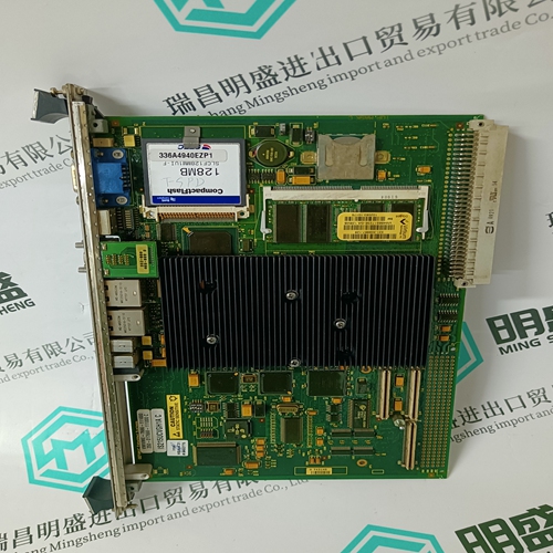
Home > Product > Robot control system > SAT RM3141-01-02 robot card
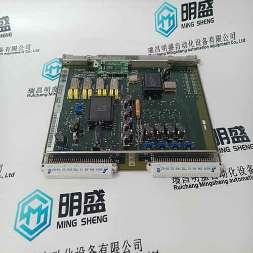
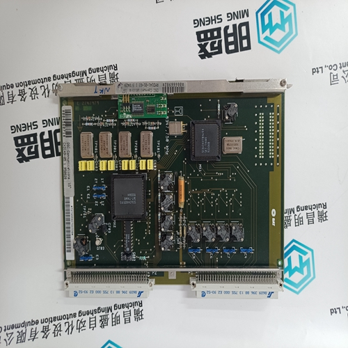
SAT RM3141-01-02 robot card
- Product ID: RM3141-01-02
- Brand: SAT
- Place of origin: the United States
- Goods status: new/used
- Delivery date: stock
- The quality assurance period: 365 days
- Phone/WhatsApp/WeChat:+86 15270269218
- Email:stodcdcs@gmail.com
- Tags:SATRM3141-01-02robot card
- Get the latest price:Click to consult
The main products
Spare parts spare parts, the DCS control system of PLC system and the robot system spare parts,
Brand advantage: Allen Bradley, BentlyNevada, ABB, Emerson Ovation, Honeywell DCS, Rockwell ICS Triplex, FOXBORO, Schneider PLC, GE Fanuc, Motorola, HIMA, TRICONEX, Prosoft etc. Various kinds of imported industrial parts
Products are widely used in metallurgy, petroleum, glass, aluminum manufacturing, petrochemical industry, coal mine, papermaking, printing, textile printing and dyeing, machinery, electronics, automobile manufacturing, tobacco, plastics machinery, electric power, water conservancy, water treatment/environmental protection, municipal engineering, boiler heating, energy, power transmission and distribution and so on.
SAT RM3141-01-02 robot card
The Generator Load Rejection logic along with Woodward’s PID_OPTI block automatically react to large load drop events to reduce valve demand (energy) to minimize speed overshoot and prevent an overspeed trip when a load rejection occurs. For a generator application there are 2 types of events that result in large load transients. Event 1—At Generator Breaker Opening: This case is typically a ‘full load’ rejection of a unit running in Unit Load Control (Droop) against a Utility grid and all load of the steam turbine is lost. When the Generator Breaker is opened, and the speed exceeds more than 1% above rated speed, the control will immediately drive the HP valve demand to zero (0%). It will hold the valve at zero until the turbine speed decreases back to a level that is with 1% of the speed setpoint. This speed setpoint is identified as the Generator Breaker Open Setpoint and is defaulted to be 50 rpm below rated speed. Event 2—At Utility Breaker Opening (with GEN Breaker still closed): In this case, a unit that is normally running in Unit Load Control (Droop), against a utility, loses the Utility breaker, but the Generator breaker remains closed and the unit is switched to ‘Island mode’. In this case there is usually still some load on the turbine. When the Utility Breaker is opened, and the speed exceeds more than 1% above rated speed, the control will immediately drive the HP valve demand to zero (0%). It will hold the valve at zero until the turbine speed decreases back to a level that is with 1% of the speed setpoint. This speed setpoint is this case is rated speed.
Feed-Forward Input
For 505 controllers configured for compressor applications, it is possible to experience a coupling effect between an anti-surge controller (external) and the 505’s internal Speed or Cascade PID controllers. If a plant condition exists where the anti-surge controller is required to open and control the anti-surge valve, compressor suction pressure will change. If the 505 Cascade controller is also controlling the compressor suction pressure, it will then respond to this pressure change, resulting in the two controllers temporarily affecting (fighting) each other. The 505 is capable of being configured to use an analog input (feed-forward signal) from an anti-surge controller. This input allows the 505 controller to decouple the response of its Speed and Cascade PID controls from that of the anti-surge controller, allowing for increased system stability in all conditions. Refer to this manual’s Speed Controller block diagram to better understand how this input is applied within the 505’s controller logic. This signal should represent the anti-surge controller’s anti-surge valve demand where 0% = 4 mA = Closed and 100% = 20 mA = Open. Delays in this signal should be kept to a minimum. This Feed-Forward function is only active when operating within the normal operating range (between Min Gov and Max Gov) and when it has been enabled. This function can be enabled/disabled through a contact input, programmable function key, or Modbus communications.
When enabled
if the feed forward analog input increases or decreases, the speed set point will be increased or decreased respectively. This is an offset added to or subtracted from the speed set point. After a feed-forward event, this speed offset will slowly ramp back to zero based on the delay time configured (typically 120 seconds). For example, if the max offset is 100 rpm with the max forward rate at 50%/s and the min offset is –75 rpm with the min forward rate at –25%/s and “Action Delay” is set to 120 seconds, then the following events describe the feed-forward action: 1. The speed set point is at Rated speed, X rpm. 2. The Feed-Forward Analog Input increases by 50% in one second. 3. The speed set point is instantly increased by 100 rpm. 4. The set point slowly decreases back to X rpm (at least 120 seconds). 5. The Feed-Forward Analog Input decreases by 25% in one second. 6. The speed set point is lowered by 75 rpm. 7. The set point slowly increases back to X rpm taking at least 120 seconds. The feed-forward loop can be configured for a temporary response, as described here, or as a direct action (continuous deviation based on the incoming signal).
