Home > Product > Robot control system > STEC S83-1003-01 switch interface module
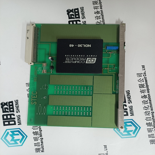
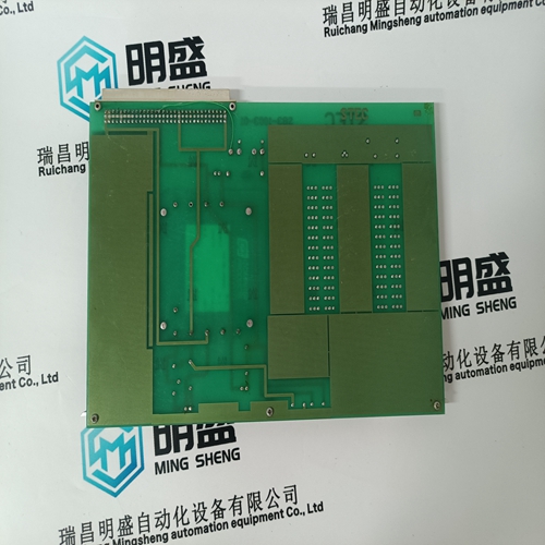
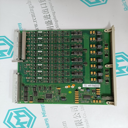
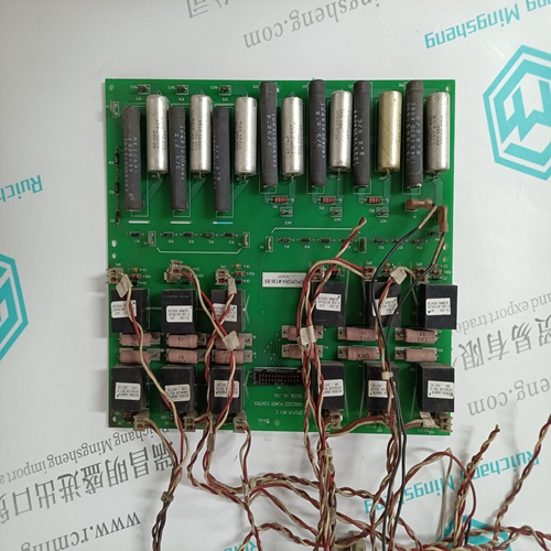
STEC S83-1003-01 switch interface module
- Product ID: S83-1003-01
- Brand: STEC
- Place of origin: the United States
- Goods status: new/used
- Delivery date: stock
- The quality assurance period: 365 days
- Phone/WhatsApp/WeChat:+86 15270269218
- Email:stodcdcs@gmail.com
- Tags:STECS83-1003-01switch interface module
- Get the latest price:Click to consult
The main products
Spare parts spare parts, the DCS control system of PLC system and the robot system spare parts,
Brand advantage: Allen Bradley, BentlyNevada, ABB, Emerson Ovation, Honeywell DCS, Rockwell ICS Triplex, FOXBORO, Schneider PLC, GE Fanuc, Motorola, HIMA, TRICONEX, Prosoft etc. Various kinds of imported industrial parts
Products are widely used in metallurgy, petroleum, glass, aluminum manufacturing, petrochemical industry, coal mine, papermaking, printing, textile printing and dyeing, machinery, electronics, automobile manufacturing, tobacco, plastics machinery, electric power, water conservancy, water treatment/environmental protection, municipal engineering, boiler heating, energy, power transmission and distribution and so on.
STEC S83-1003-01 switch interface module
Emergency Loop In case of a compressor surge event, a large speed upset may occur, and recovery may be very difficult. If this event occurs, Emergency Feed-Forward action can be programmed to instantly bias the control’s speed reference using a larger offset than the regular feed-forward loop. When configured, the Emergency Feed-Forward bias action will increase the anti-surge controller’s effect for a short period, configured as the ‘Emergency Action Delay’, to assist the anti-surge controller with protecting the compressor. The Emergency Action takes effect when the Feed-Forward Analog Input increases or decreases faster than the configured ‘FW Rate to Activate’ (this should be larger than the ‘Min/Max Forward Rate’ used for the regular Feed Forward loop). The ‘Emergency Max Speed Offset’ will be added to the speed reference. This offset immediately begins ramping down and will reach zero after the configured ‘Emergency Action Delay’. At this point, only the normal feed forward action offset will be in effect since the emergency will typically have a much shorter duration
Direct Action
When configured for direct action, the feed-forward loop will offset the speed set point proportional to its 4–20 mA calibration. This offset will not ramp back to zero; it remains active and offsets the speed reference based on the actual value of the Feed-Forward Analog Input. For example, if configured for a max offset of 150 rpm and a min offset of –50 rpm, then Direct Feed-Forward action offsets the set point by 0 rpm if the analog input is at 8 mA. The offset is 100 rpm if the analog input is at 16 mA, and the offset will not ramp down to 0; it remains at 100 rpm as long as the analog input is at 16 mA. The direct action cannot be used to decrease speed below Min governor and above Max Governor.
The selection of the Process Variable to use for this control is: Cascade Analog Input KW/Load Input Inlet Steam Pressure Exhaust Steam Pressure Cascade control may be enabled and disabled from the 505 keypad, a contact input, or Modbus communications. The last command given from any of these three sources dictates the Cascade PID’s control state. If a contact input is programmed to function as a Cascade Enable contact, when the contact is open Cascade control is disabled, and when it is closed Cascade control is enabled. This contact can either be open or closed when a trip condition is cleared. If the contact is open it must be closed to enable Cascade control. If the contact is closed it must be opened and re-closed to enable Cascade control.
Cascade Control
The Cascade control can be configured to control any system process, related to or affected by turbine speed or load. Typically this controller is configured and used as a turbine inlet, or exhaust pressure controller. Cascade control is a PID controller that is cascaded with the Speed PID. The Cascade PID compares a 4–20 mA process signal with an internal set point to directly position the speed set point, thus changing turbine speed or load until the process signal and set point match. By Cascading two PIDs in this fashion, a bumpless transfer between the two controlling parameters can be performed. When enabled, the Cascade PID can move the speed set point at a variable rate up to the ‘Max Speed Set Point Rate’ setting (programmed under the CASCADE CONTROL header).
Since Cascade is a secondary speed setting function, the Speed PID must be in control of the 505’s LSS bus in order for Cascade to take control. When the 505 is configured for a generator application, both the utility tie and generator breakers must be closed, before the Cascade PID can begin controlling a process.

