Home > Product > Robot control system > TEAM BG0090 Automation module
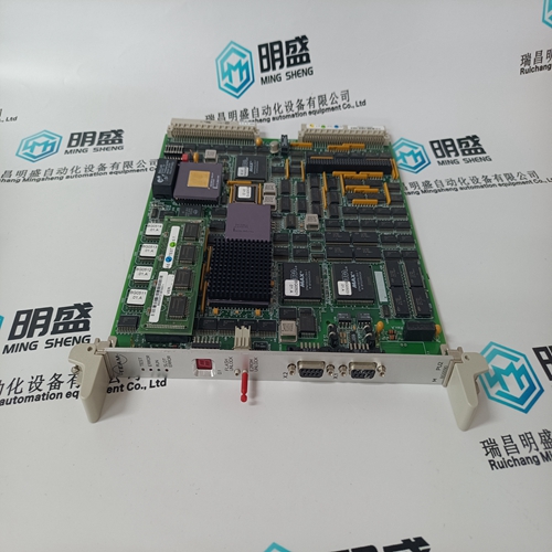
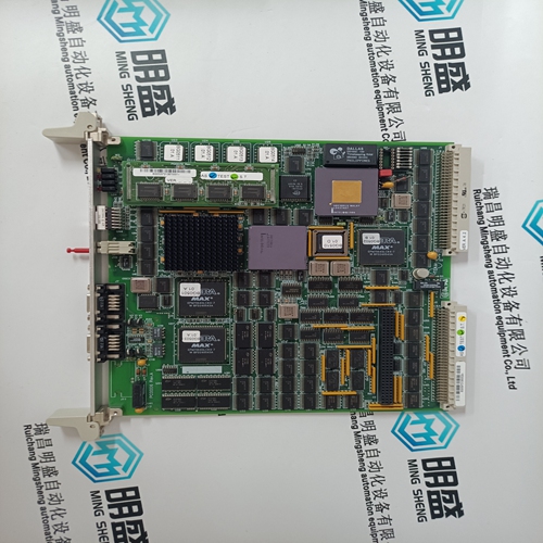
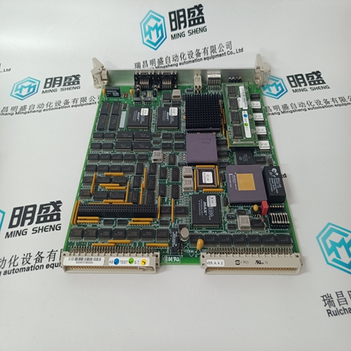
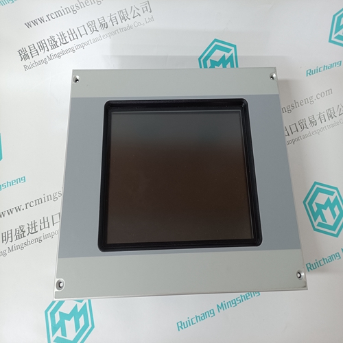
TEAM BG0090 Automation module
- Product ID: BG0090
- Brand: TEAM
- Place of origin: the United States
- Goods status: new/used
- Delivery date: stock
- The quality assurance period: 365 days
- Phone/WhatsApp/WeChat:+86 15270269218
- Email:stodcdcs@gmail.com
- Tags:TEAMBG0090Automation module
- Get the latest price:Click to consult
The main products
Spare parts spare parts, the DCS control system of PLC system and the robot system spare parts,
Brand advantage: Allen Bradley, BentlyNevada, ABB, Emerson Ovation, Honeywell DCS, Rockwell ICS Triplex, FOXBORO, Schneider PLC, GE Fanuc, Motorola, HIMA, TRICONEX, Prosoft etc. Various kinds of imported industrial parts
Products are widely used in metallurgy, petroleum, glass, aluminum manufacturing, petrochemical industry, coal mine, papermaking, printing, textile printing and dyeing, machinery, electronics, automobile manufacturing, tobacco, plastics machinery, electric power, water conservancy, water treatment/environmental protection, municipal engineering, boiler heating, energy, power transmission and distribution and so on.
TEAM BG0090 Automation module
All pertinent cascade control parameters are available through the Modbus links, refer to Chapter 6 for a complete listing of Modbus parameters. Cascade Dynamics The Cascade PID control uses its own set of dynamic settings. These values are programmable and may be tuned at any time. Refer to the PID Dynamic Adjustments section in this manual. Cascade Set Point The Cascade set point can be adjusted from the 505 keypad, external contacts, Modbus commands, or through a 4–20 mA analog input. A specific setting can also be directly entered from the 505 keypad or through Modbus commands. The Cascade set point range must be defined in the program mode. Program settings ‘Min Cascade Set Point’ and ‘Max Cascade Set Point’ define the range of the Cascade set point and control.Cascade set point raise/lower contact inputs act as speed set point raise/lower contacts when Cascade is not active or in control. This allows a single set of contacts (one SPDT switch) to control the Speed set point when the generator breaker is open, the load set point when paralleled to a utility, and the Cascade set point when enabled. Alternatively, a second set of contacts (speed raise and lower) could be used to independently control the speed and load set points.
Cascade Control Status Messages
Cascade is Disabled—Cascade control is not enabled and will have no effect. Cascade is Enabled—Cascade has been enabled but is not active or in control. Permissives have not been met (speed < min gov, generator or tie breaker open). Casc Active/Not Spd Ctl—Cascade has been enabled but the Speed PID is not in control of the LSS bus (either aux or valve limiter is in control). Cascade is In Control—Cascade is in control of the LSS bus.
Casc Active w/Rmt Setpt—Cascade has been enabled and the Remote Cascade set point is in control of the set point but the Speed PID is not in control of the LSS bus. Casc Control w/Rmt Setpt—Cascade is in control of the LSS bus (via the Speed PID) and the Remote Cascade Set Point is positioning the Cascade set point. Cascade is Inhibited—Cascade cannot be enabled; the Cascade input signal has failed, a controlled stop is selected, the unit is shut down, or cascade control is not programmed. Cascade control is automatically disabled on a shutdown condition, and must be re-enabled after a successful system start-up. Cascade control is disabled if Remote Speed Set Point is used and enabled. Should another parameter on the LSS bus take control of governor valve position from the Speed PID, Cascade control will stay active, and begin controlling again when the Speed PID is the lowest parameter on the LSS bus again.
A specific set point
may also be directly entered from the 505 keypad or through Modbus communications. When this is performed, the set point will ramp at the ‘Casc Setpt Rate’ (as defaulted in Service mode). To “enter” a specific set point from the 505 keypad, press the CAS key to view the Cascade control screen, press the ENTER key, enter the set point level desired, then press the ENTER key again. If a valid number was entered, equal-to or between the min and max set point settings, the setting will be accepted and the Cascade set point will ramp to the “entered” set point level. If an invalid number is “entered”, the setting will not be accepted and the 505’s screen will momentarily display a value out-ofrange message. When a valid set point value is entered, the set point will ramp at the Cascade Set Point Rate to the newly entered set point value. This ‘Entered’ rate is tunable through the Service mode.
When a raise or lower Cascade Set Point command is issued, the set point moves at the programmed ‘Casc Setpt Rate’ setting. If a Cascade raise or lower command is selected for longer than three seconds, the Cascade set point will move at the fast rate which is three times the cascade set point rate. The Cascade set point rate, fast rate delay, and fast rate can all be adjusted in the Service mode. The shortest length of time a set point will move for an accepted raise or lower command is 40 milliseconds (120 milliseconds for a Modbus command). If the Cascade set point slow rate is programmed for 10 psi/s, the smallest increment it will move is 0.4 psi (1.2 psi for Modbus).