Home > Product > DCS control system > ACU-01B 3HNA024871-001/03 controller
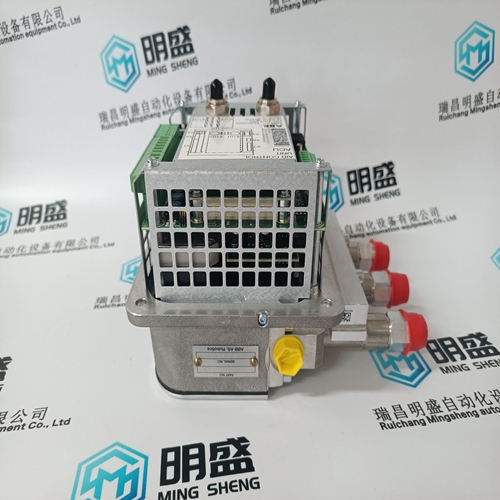
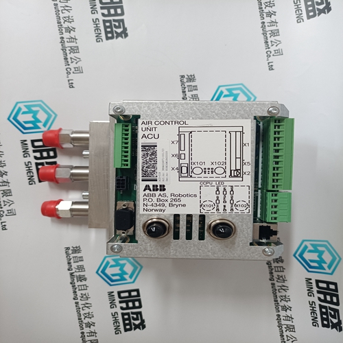
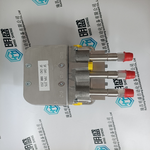
ACU-01B 3HNA024871-001/03 controller
- Product ID: ACU-01B 3HNA024871-001/03
- Brand: ABB
- Place of origin: The Swiss
- Goods status: new/used
- Delivery date: stock
- The quality assurance period: 365 days
- Phone/WhatsApp/WeChat:+86 15270269218
- Email:stodcdcs@gmail.com
- Tags:ACU-01B 3HNA024871-001/03controller
- Get the latest price:Click to consult
The main products
Spare parts spare parts, the DCS control system of PLC system and the robot system spare parts,
Brand advantage: Allen Bradley, BentlyNevada, ABB, Emerson Ovation, Honeywell DCS, Rockwell ICS Triplex, FOXBORO, Schneider PLC, GE Fanuc, Motorola, HIMA, TRICONEX, Prosoft etc. Various kinds of imported industrial parts
Products are widely used in metallurgy, petroleum, glass, aluminum manufacturing, petrochemical industry, coal mine, papermaking, printing, textile printing and dyeing, machinery, electronics, automobile manufacturing, tobacco, plastics machinery, electric power, water conservancy, water treatment/environmental protection, municipal engineering, boiler heating, energy, power transmission and distribution and so on.
ACU-01B 3HNA024871-001/03 controller
If no external contact input or function keys are programmed for the ‘Enable’ commands, Cascade Control and Remote Cascade Control must be enabled from either the front panel keypad or from Modbus. Since the front panel and Modbus provide both Remote Cascade Enable and Cascade Control Enable commands, they will operate in the same manner as ‘both enables programmed’. Refer to Volume 2 of this manual for information on related Service mode tunables. All pertinent Remote Cascade control parameters are available through the Modbus links. See Chapter 6 for a complete listing of Modbus parameters.
For generator applications, Auxiliary control limiting can be configured to be disabled when the generator and/or utility tie breakers are open. Program settings ‘Generator Breaker Open Aux Disable’ and ‘Tie Breaker Open Aux Disable’ may be configured to deactivate Auxiliary PID limiting, depending on system breaker positions. When both settings are programmed as unchecked (NO), the Auxiliary limiter will always stay ‘active’. If either setting is programmed as checked (YES), the Auxiliary limiter will be active only when the tie breaker or generator breaker respectively, is closed. If the unit is not configured for a generator application, the utility tie and generator breaker inputs do not affect Auxiliary limiter status, and the Limiter will be active at all times.
Auxiliary Control
The Auxiliary PID controller can be used to limit or control generator power, plant import/export power, turbine inlet pressure, turbine exhaust pressure, pump/compressor discharge pressure, or any other auxiliary parameters, directly related to turbine speed/load. The selection of the Process Variable to use for this control is: Auxiliary Analog Input KW/Load Input Inlet Steam Pressure Exhaust Steam Pressure Each of these inputs is a 4 to 20 mA current signal (the KW/Load could be from a ‘Woodward Links’ digital communication link). The PID control amplifier compares this input signal with the Auxiliary set point to produce a control output to the digital LSS (low-signal select) bus. The LSS bus sends the lowest signal to the actuator driver circuitry. The Auxiliary set point is adjustable with raise or lower commands through the 505 front keypad, through remote contact inputs or through Modbus. Also, the set point can be directly set by entering the new set point from the keypad or through Modbus communications. In addition, an analog input can be programmed to remotely position the Auxiliary set point.
Auxiliary as a Limiter
When configured as a limiter, the Auxiliary control is low signal selected (LSS) with all of the other PIDs, allowing it to limit turbine speed/load based on any auxiliary parameter which is directly related. To configure the Auxiliary controller to function as a limiter, do NOT check the configuration parameter of ‘Use Aux as Controller’. When Auxiliary is configured to act as a limiter the Auxiliary PID will ‘limit’ the LSS bus when the input reaches the set point. The Aux set point initializes to the programmed ‘Setpoint Initial Value’ setting on a power-up-reset. This set point may be adjusted at any time and will remain at a setting (running or shutdown), provided a power-up-reset did not occur. Depending on configuration and system conditions, the Auxiliary Limiter may be in one of the following states (505 front panel screen messages): Auxiliary is Enabled—Auxiliary has been enabled but the generator and utility tie breaker permissives have not been met (generator applications only). Aux Active/Not Lmting—Auxiliary is configured as a limiter but is not limiting the LSS bus. Aux Active w/Rmt Setpt—Auxiliary is not in control of the LSS bus and the remote Auxiliary input is in command of the set point. Aux Control w/Rmt Setpt—Auxiliary is in limiting the LSS bus and the remote Auxiliary analog input is in command of the set point. Auxiliary is Inhibited—Auxiliary cannot be enabled. The input signal has failed.
