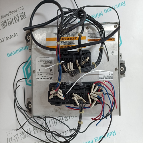
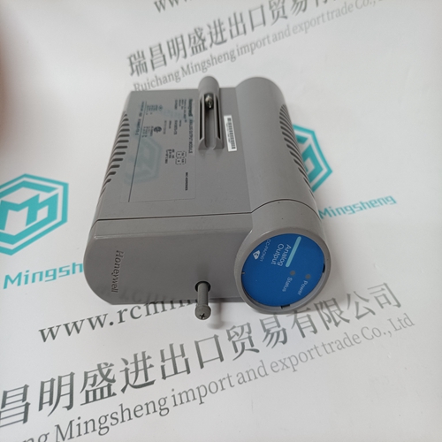
Home > Product > PLC programmable module > BENTLY 125840-01 Monitor card
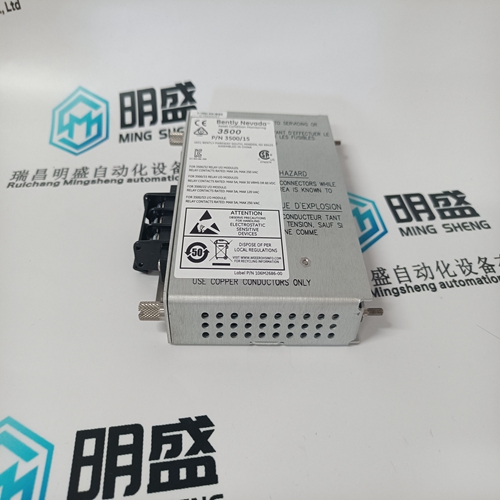
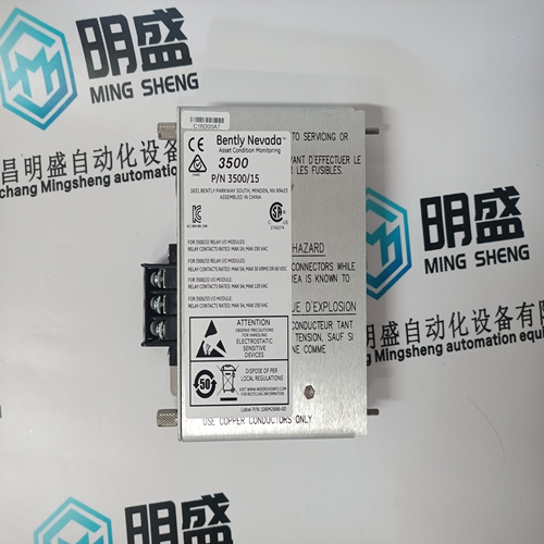
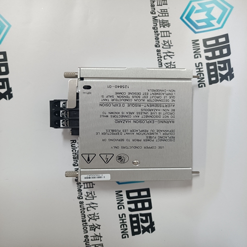
BENTLY 125840-01 Monitor card
- Product ID: 125840-01
- Brand: BENTLY
- Place of origin: the United States
- Goods status: new/used
- Delivery date: stock
- The quality assurance period: 365 days
- Phone/WhatsApp/WeChat:+86 15270269218
- Email:stodcdcs@gmail.com
- Tags:BENTLY125840-01Monitor card
- Get the latest price:Click to consult
The main products
Spare parts spare parts, the DCS control system of PLC system and the robot system spare parts,
Brand advantage: Allen Bradley, BentlyNevada, ABB, Emerson Ovation, Honeywell DCS, Rockwell ICS Triplex, FOXBORO, Schneider PLC, GE Fanuc, Motorola, HIMA, TRICONEX, Prosoft etc. Various kinds of imported industrial parts
Products are widely used in metallurgy, petroleum, glass, aluminum manufacturing, petrochemical industry, coal mine, papermaking, printing, textile printing and dyeing, machinery, electronics, automobile manufacturing, tobacco, plastics machinery, electric power, water conservancy, water treatment/environmental protection, municipal engineering, boiler heating, energy, power transmission and distribution and so on.
BENTLY 125840-01 Monitor card
The Speed PID will only track the Auxiliary PID LSS bus signal up to 100% speed/load. Thus if turbine speed/load reaches 100%, the Speed PID will protect the unit by limiting unit speed/load to less than or equal to 100%. Depending on the configuration and system conditions, the Auxiliary PID may be in one of the following states (505 front panel screen messages): Auxiliary is Disabled—Auxiliary is disabled and will have no effect on the LSS bus. Auxiliary is Enabled—Auxiliary has been enabled but the generator and utility tie breaker permissives have not been met (generator applications only). Aux Active/Not in Ctrl—Auxiliary has been enabled, permissives met, but is not in control of the LSS bus. Aux Active w/Rmt Setpt—Auxiliary has been enabled but is not in control of the LSS bus and the remote Auxiliary input is controlling the set point. Auxiliary in Control—Auxiliary is in control of the LSS bus. Aux Control w/Rmt Setpt—Auxiliary is in control of the LSS bus and the remote Auxiliary analog input is in control of the set point. Auxiliary is Inhibited—Auxiliary cannot be enabled; input signal is failed, 505 is in Frequency Control, controlled shutdown is selected, unit is shut down or Auxiliary control is not programmed.
Auxiliary as a Controller (using Enable/Disable)
When configured as a controller, the Auxiliary PID may enabled and disabled on command. With this configuration, when Auxiliary control is enabled it instantly takes full control of the LSS bus, and the Speed PID is switched to a tracking mode. When Auxiliary control is disabled the Speed PID instantly takes full control of the LSS bus. To allow a bumpless transfer between modes, when the Auxiliary PID is enabled, the Speed PID tracks a few % above the Auxiliary PID’s LSS bus signal. When the Auxiliary PID is disabled, its set point tracks the Auxiliary PID’s process signal. To configure the Auxiliary controller to function as a controller, check the configuration box ‘Use Aux as Controller’ on the Auxiliary Control configuration page.
For generator applications, Auxiliary control can be configured to be disabled when the generator and/or utility tie breakers are open. Program settings ‘Generator Breaker Open Aux Disable’ and ‘Tie Breaker Open Aux Disable’ may be configured to deactivate Auxiliary PID control, depending on system breaker positions. When both settings are programmed as unchecked (NO), the Auxiliary limiter will always stay ‘active’. If either setting is programmed as checked (YES), the Auxiliary limiter will be active only when the tie breaker or generator breaker respectively, is closed. If the unit is not configured for a generator application, the utility tie and generator breaker inputs do not affect Auxiliary control status, and the controller will be active at all times (capable of being enabled).
Auxiliary Dynamics
The Auxiliary PID control uses its own set of dynamic settings. These values are programmable and may be tuned at any time. Refer to the PID Dynamic Adjustments section in this manual.
Auxiliary control may be enabled from the 505 keypad (GUI), remote contacts, or Modbus/OPC communications. The last command given from any of these three sources dictates which state the Auxiliary control is in. If an external Auxiliary Enable contact is programmed, disable is selected when the contact is open and enable is selected when it is closed. The contact can be either open or closed when a trip condition is cleared. If the contact is open it must be closed to enable. If the contact is closed it must be opened and re-closed to enable. When configured as enable/disable controller, the Auxiliary control will automatically be disabled upon a shutdown condition. Auxiliary control will be disabled and inhibited when the 505 is in frequency control. If the Process Variable (PV) milliamp input signal is out of range (below 2 mA or above 22 mA) an alarm will occur and Auxiliary control will be inhibited until the input signal is corrected and the alarm is cleared. Optionally the unit can be programmed to issue a shutdown on a loss of the Auxiliary input process variable signal.