Home > Product > Gas turbine system > ISX2YUCSAH1A 336A4940LBP92 Gas turbine module
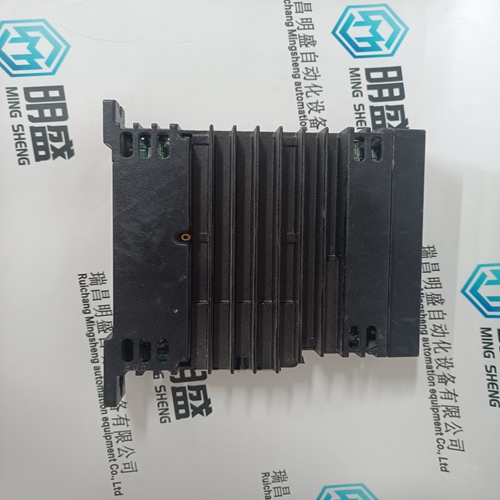
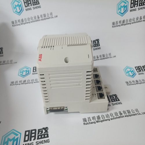
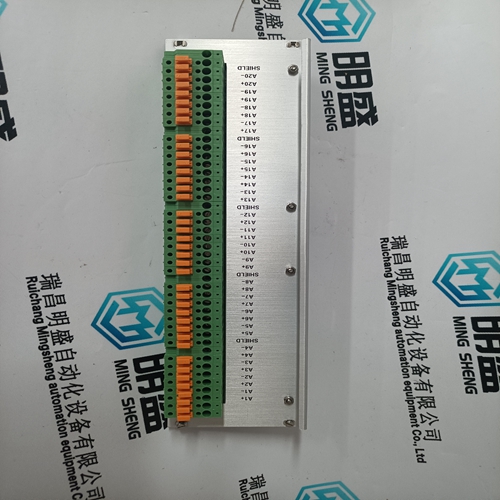
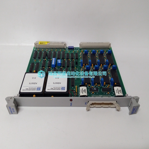
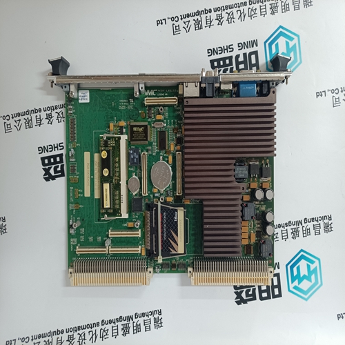
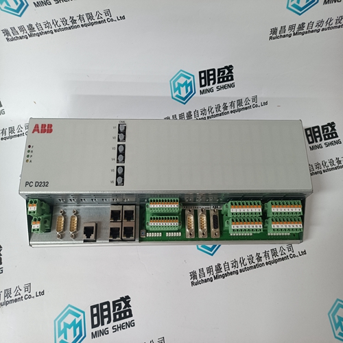
ISX2YUCSAH1A 336A4940LBP92 Gas turbine module
- Product ID: ISX2YUCSAH1A 336A4940LBP92
- Brand: GE
- Place of origin: the United States
- Goods status: new/used
- Delivery date: stock
- The quality assurance period: 365 days
- Phone/WhatsApp/WeChat:+86 15270269218
- Email:stodcdcs@gmail.com
- Tags:ISX2YUCSAH1A 336A4940LBP92Gas turbine module
- Get the latest price:Click to consult
The main products
Spare parts spare parts, the DCS control system of PLC system and the robot system spare parts,
Brand advantage: Allen Bradley, BentlyNevada, ABB, Emerson Ovation, Honeywell DCS, Rockwell ICS Triplex, FOXBORO, Schneider PLC, GE Fanuc, Motorola, HIMA, TRICONEX, Prosoft etc. Various kinds of imported industrial parts
Products are widely used in metallurgy, petroleum, glass, aluminum manufacturing, petrochemical industry, coal mine, papermaking, printing, textile printing and dyeing, machinery, electronics, automobile manufacturing, tobacco, plastics machinery, electric power, water conservancy, water treatment/environmental protection, municipal engineering, boiler heating, energy, power transmission and distribution and so on.
ISX2YUCSAH1A 336A4940LBP92 Gas turbine module
Invert Auxiliary Input Depending on the control action required, the Auxiliary PID’s input signal can be inverted. If a decrease in inlet control valve position is required to increase the Auxiliary process signal, program the ‘INVERT AUX INPUT’ setting to ‘YES’. An example of this control action would be when the Auxiliary PID is configured to control turbine inlet steam pressure. To increase turbine inlet steam pressure, inlet control valve position must be decreased.
A specific set point may also be directly entered from the 505 keypad or through Modbus/OPC communications. When this is performed, the set point will ramp at the ‘Auxiliary Setpoint Rate’ (as defaulted in Service mode). To “enter” a specific set point from the 505 Display use the following steps: 1. From the HOME page go to the Auxiliary Control page 2. Press the Commands button until ‘Entered Setpoint’ appears 3. Select ‘Entered Setpoint’ and a pop-up will appear 4. Press Enter from the Navigation cross and the pop-up value will highlight 5. Adjust the value with the Adjust keys or enter a value from the keypad 6. Press Enter again when desired value has been entered 7. The value in the pop-up will be accepted, if it is invalid a message will appear 8. Select the GO button to ramp the setpoint to this entered value
Generator Load Limiter/Control
On generator applications, the Auxiliary PID may be programmed to use the ‘KW/Unit Load Input’ signal instead of the Auxiliary input signal for limiting or control. This is the same input signal (KW/Unit Load input) used by the Speed PID for KW droop. This configuration allows the Auxiliary PID to limit or control generator power. Auxiliary Droop When sharing control of a parameter with another external controller, the Auxiliary control amplifier can also receive a programmable DROOP feedback signal for control loop stability. This feedback signal is a percentage of the LSS bus (control valve position). By including this second parameter into the control loop, the Auxiliary PID becomes satisfied, and does not fight with the other external controller over the shared parameter. The Droop % fed back to the Auxiliary PID is equal to the following defaulted settings: LSS BUS OUTPUT % x ‘AUXILIARY DROOP %’ x ‘MAX AUX SET POINT’ x 0.0001 Example: 25% x 5% x 600 psi x 0.0001 = 7.5 psi Where the ‘AUX DROOP %’ is set in Program mode, ‘MAX AUX SET POINT’ value is determined by the upper range limit of the process variable selected and the ‘LSS bus output %’ is determined by the Auxiliary demand.
Auxiliary Set Point
The Auxiliary set point can be adjusted from the 505 keypad, external contacts, Modbus/OPC commands, or through a 4–20 mA analog input. A specific setting can also be directly entered from the 505 keypad or through Modbus commands. The Auxiliary set point range must be defined in the program mode. Program settings ‘Minimum Auxiliary Setpoint’ and ‘Maximum Auxiliary Setpoint’’ define the range of the Auxiliary set point and control. When a raise or lower Auxiliary Set Point command is issued, the set point moves at the programmed ‘Auxiliary Setpoint Rate’ setting. If a Auxiliary raise or lower command is selected for longer than three seconds, the Auxiliary set point will move at three times at the fast rate which is three times the Auxiliary set point rate. The Auxiliary set point rate, fast rate delay, and fast rate can all be adjusted in the Service mode. The shortest length of time a set point will move for an accepted raise or lower command is 40 milliseconds (120 milliseconds for a Modbus command
Refer to Volume 2 of this manual for further information on Service mode and online tunables. All pertinent auxiliary control parameters are available through the Modbus links. See Chapter 6 for a complete listing of Modbus parameters.