Home > Product > DCS control system > TRICONEX 3625A Communication module
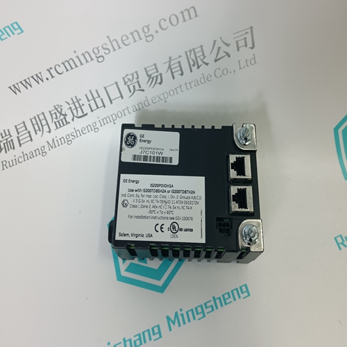
TRICONEX 3625A Communication module
- Product ID: 3625A
- Brand: TRICONEX
- Place of origin: The United States
- Goods status: new/used
- Delivery date: stock
- The quality assurance period: 365 days
- Phone/WhatsApp/WeChat:+86 15270269218
- Email:stodcdcs@gmail.com
- Tags:TRICONEX3625ACommunication module
- Get the latest price:Click to consult
The main products
Spare parts spare parts, the DCS control system of PLC system and the robot system spare parts,
Brand advantage: Allen Bradley, BentlyNevada, ABB, Emerson Ovation, Honeywell DCS, Rockwell ICS Triplex, FOXBORO, Schneider PLC, GE Fanuc, Motorola, HIMA, TRICONEX, Prosoft etc. Various kinds of imported industrial parts
Products are widely used in metallurgy, petroleum, glass, aluminum manufacturing, petrochemical industry, coal mine, papermaking, printing, textile printing and dyeing, machinery, electronics, automobile manufacturing, tobacco, plastics machinery, electric power, water conservancy, water treatment/environmental protection, municipal engineering, boiler heating, energy, power transmission and distribution and so on.
TRICONEX 3625A Communication module
When both Remote Auxiliary Enable and Auxiliary Control Enable commands are programmed, each function is enabled by its respective command selection. If Remote Auxiliary Enable is selected, only the Remote Auxiliary Set Point will be enabled. If Auxiliary Control Enable is selected, only Auxiliary control will be enabled. If Remote Auxiliary Disable is selected, only the Remote Auxiliary Set Point will be disabled. If Auxiliary Control Disable is selected, both Remote Auxiliary control and Auxiliary control will be disabled. However, if before the Auxiliary PID was ‘In-control’ an Auxiliary Disable command is given, only Auxiliary control will be disabled. If no external contact inputs are programmed for the ‘Enable’ commands, Auxiliary Control and Remote Auxiliary Control must be enabled from either the front panel keypad or from Modbus. Since the front panel and Modbus provide both Remote Auxiliary Enable and Auxiliary Control Enable commands, they will operate in the same manner as ‘both enables programmed’. Refer to Volume 2 of this manual for information on related Service mode tunables. All pertinent Remote Auxiliary Set Point parameters are available through the Modbus links. See Chapter 6 for a complete listing of Modbus parameters.
Auxiliary 2 Control
The Auxiliary 2 PID controller can be used to limit generator power, plant import/export power, turbine inlet pressure, turbine exhaust pressure, pump/compressor discharge pressure, or any other auxiliary parameters, directly related to turbine speed/load. The selection of the Process Variable to use for this control is: Auxiliary Analog Input KW/Load Input Inlet Steam Pressure Exhaust Steam Pressure Each of these inputs is a 4 to 20 mA current signal (the KW/Load could be from a ‘Woodward Links’ digital communication link). The PID control amplifier compares this input signal with the Auxiliary set point to produce a control output to the digital LSS (low-signal select) bus. The LSS bus sends the lowest signal to the actuator driver circuitry. This control works exactly the same as the Auxiliary Control (last section) with the exception that it can only be a limiter and not a controller.The valve limiter, limits the actuator output signal (governor valve position) to aid in starting up and shutting down the turbine. The output of the valve limiter is Low-Signal-Selected with the output of the Speed and Auxiliary PIDs. The PID or limiter asking for the lowest valve position will control valve position. Thus, the valve limiter, limits the maximum valve position. The valve limiter can also be used to trouble shoot system dynamics problems. If it is believed that the 505 is the source of system instability, the valve limiter can be positioned to manually take control of the valve position. Care should be taken when using the valve limiter in this fashion, so as to not allow the system to reach a dangerous operating point.
The valve limiter level
is adjusted through the 505 keypad, contact input, or through Modbus communications. When raise or lower commands are received, the limiter ramps up or down, at the ‘VALVE LIMITER RATE’. The maximum the limiter can increase is 100%. The Valve Limiter ‘Rate’ and ‘Max Valve position’ settings can be adjusted in the Service mode. A specific set point may also be directly entered from the 505 keypad or through Modbus communications. When this is performed, the set point will ramp at the ‘Valve Limiter Rate’ (as defaulted in Service mode). To “enter” a specific set point from the 505 keypad, press the LMTR key to view the Valve Limiter screen, press the ENTER key, enter the set point level desired, then press the ENTER key again. If a valid number was entered, equal-to or between the min and max set point settings, the setting will be accepted and the Valve Limiter will ramp to the “entered” level. If an invalid number is “entered”, the setting will not be accepted and the 505’s screen will momentarily display a value out-of-range message. To “enter” a specific set point from the 505 Display use the following steps: 1. From the HOME page go to the Auxiliary Control page 2. Press the Commands button until ‘Entered Setpoint’ appears 3. Select ‘Entered Setpoint’ and a pop-up will appear 4. Press Enter from the Navigation cross and the pop-up value will highlight 5. Adjust the value with the Adjust keys or enter a value from the keypad 6. Press Enter again when desired value has been entered 7. The value in the pop-up will be accepted, if it is invalid a message will appear 8. Select the GO button to ramp the setpoint to this entered value