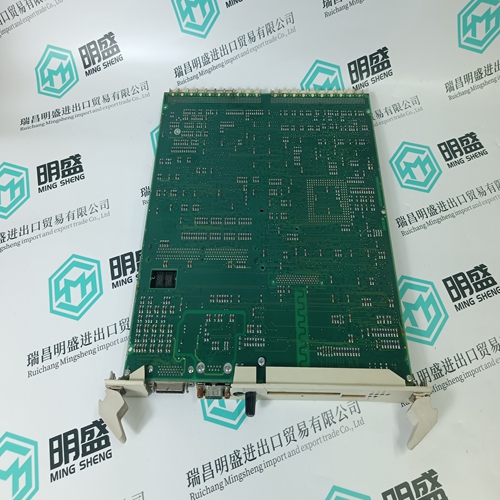
Home > Product > DCS control system > A4H124-24TX switches
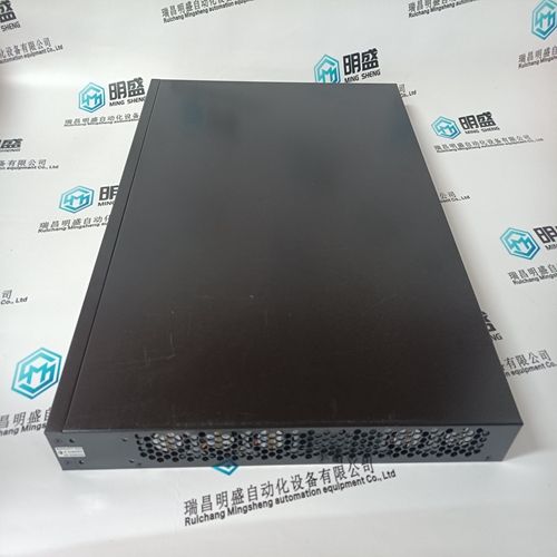
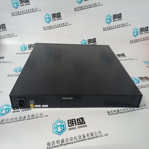
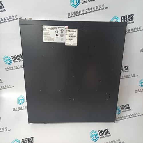
A4H124-24TX switches
- Product ID: A4H124-24TX
- Brand: FOXBORO
- Place of origin: The United States
- Goods status: new/used
- Delivery date: stock
- The quality assurance period: 365 days
- Phone/WhatsApp/WeChat:+86 15270269218
- Email:stodcdcs@gmail.com
- Tags:A4H124-24TXswitches
- Get the latest price:Click to consult
The main products
Spare parts spare parts, the DCS control system of PLC system and the robot system spare parts,
Brand advantage: Allen Bradley, BentlyNevada, ABB, Emerson Ovation, Honeywell DCS, Rockwell ICS Triplex, FOXBORO, Schneider PLC, GE Fanuc, Motorola, HIMA, TRICONEX, Prosoft etc. Various kinds of imported industrial parts
Products are widely used in metallurgy, petroleum, glass, aluminum manufacturing, petrochemical industry, coal mine, papermaking, printing, textile printing and dyeing, machinery, electronics, automobile manufacturing, tobacco, plastics machinery, electric power, water conservancy, water treatment/environmental protection, municipal engineering, boiler heating, energy, power transmission and distribution and so on.
A4H124-24TX switches
The Shutdown Condition relay may be programmed to indicate a shutdown condition on a remote panel or to a plant DCS. The Shutdown Indication relay is normally de-energized. This relay will energize upon any shutdown condition and stay energized until all trips have been cleared. The ‘Reset Clears Trip’ function has no effect on the programmable Shutdown Indication relay. When programmed as a Trip relay, the respective relay will function like the dedicated Shutdown relay (normally energized and de-energizes on a shutdown) to indicate the position of the dedicated Shutdown relay.The Controlled Shutdown function is used to stop the turbine in a controlled manner, as opposed to an Emergency Trip. When a STOP command (controlled shutdown) is issued, the following sequence is performed: 1. Cascade and Auxiliary(if not a limiter) PID controllers are disabled 2. The Speed Set Point is ramped to min load set point at normal rate (only for generator application). 3. When at min load (only for generator application), the controller will wait until the generator breaker opens (only if “Reverse Power on Controlled Stop?” = False). If a relay output is configured as “generator open pulse (2s)”, then this relay will temporarily energize for 2 seconds. 4. The Speed Set Point is ramped to its low idle level. 5. Once the speed set point has reached its low idle point, the HP valve limiter is then ramped to zero percent at a controlled rate. At this point if the “Controlled Stop & Trip” setting is configured to “no” the control will then wait for a Start command to restart the turbine. However, if the “Controlled Stop & Trip” setting is configured to “yes” the control will then execute a turbine shutdown.
Inlet Steam Pressure Compensation
The inlet pressure compensation feature is used to adjust the control response based on variations in the inlet steam header pressure. Inlet pressure compensation is enabled in Configure Mode (under Operating Parameters). To use this feature, an analog input must be configured as inlet steam pressure. Once this is configured, the Pressure compensation curve will be available in the Service Menu screens. The compensation factor is determined by a user-defined curve. The X values of the curve points are inlet pressures in engineering units. The Y values of the curve points are a gain multiplier on the HP valve demand. By default, all Y values are initially set to 1.0. The X values should be set to the expected range of inlet pressure for normal operation, with at least one Point being the rated pressure and a gain of 1.0. Increase the gain (Y values) for pressures less than rated and decrease the gains for pressures greater than rated. This gain factor is applied to the valve demand prior to the valve linearization curve (if that option is used)
All X values entered in the curve must be increasing. The curve block has been implemented such that it will limit the gain to the first and last points entered by the user. If the inlet steam pressure signal fails, then the curve is bypassed and the gain is forced to 1.0. The gain output of this curve should be left at 1.0 (all Y values at 1.0) until the control PID gains have been tuned at the rated inlet pressure. Once this is done, then the inlet pressure compensation curve points can be set for other inlet pressures.
Emergency Shutdown
When an Emergency Shutdown condition occurs, the actuator output signal is stepped to zero milliamps, the Shutdown relay de-energizes, and the shutdown cause (first shutdown condition sensed) is displayed on the 505’s front panel. See Chapter 5 for a detailed list of the possible shutdown (Trip) conditions. Up to ten (10) Emergency Shutdown inputs (contact inputs) can be programmed to allow the 505 to indicate the cause of an emergency shutdown. By wiring trip conditions directly into the 505, instead of a trip string, the 505 can pass a trip signal directly to its output relay (to trip the T&T valve), and also indicate the first trip condition sensed. The 505’s total throughput time is 20 milliseconds (worse case). Each of these discrete input shutdown inputs will be time-stamped by the real-time clock with 1 ms resolution. All trip conditions are indicated through the 505’s front panel, and Modbus communications. The cause of the last trip is displayed by pressing the VIEW key under the TRIP LED. The last trip indication, is latched-in and can be viewed at any time after a trip and before the next trip condition is latched in. Once latched-in the last trip indication cannot be reset. This allows an operator to confirm what the trip condition was hours or days after the unit has been reset and restarted. In addition to the dedicated Shutdown relay, the other programmable relays may be configured as Shutdown condition or Trip relays.
