Home > Product > Servo control system > SYHNC100-NIB-23/W-24-P-D-E23-A012 Driver module
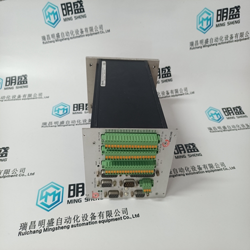
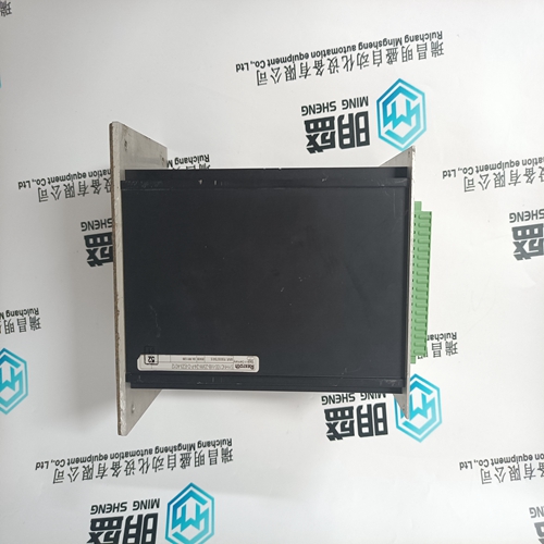
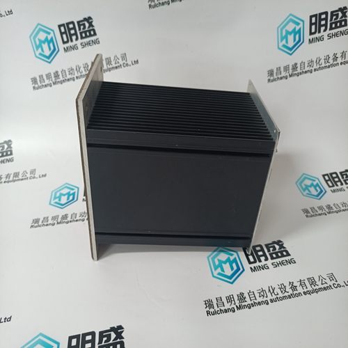
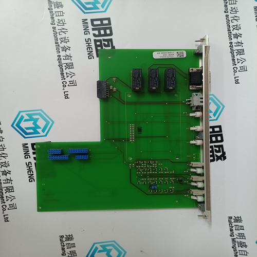
SYHNC100-NIB-23/W-24-P-D-E23-A012 Driver module
- Product ID: SYHNC100-NIB-23/W-24-P-D-E23-A012
- Brand: Rexroth
- Place of origin: the United States
- Goods status: new/used
- Delivery date: stock
- The quality assurance period: 365 days
- Phone/WhatsApp/WeChat:+86 15270269218
- Email:stodcdcs@gmail.com
- Tags:SYHNC100-NIB-23/W-24-P-D-E23-A012Driver module
- Get the latest price:Click to consult
The main products
Spare parts spare parts, the DCS control system of PLC system and the robot system spare parts,
Brand advantage: Allen Bradley, BentlyNevada, ABB, Emerson Ovation, Honeywell DCS, Rockwell ICS Triplex, FOXBORO, Schneider PLC, GE Fanuc, Motorola, HIMA, TRICONEX, Prosoft etc. Various kinds of imported industrial parts
Products are widely used in metallurgy, petroleum, glass, aluminum manufacturing, petrochemical industry, coal mine, papermaking, printing, textile printing and dyeing, machinery, electronics, automobile manufacturing, tobacco, plastics machinery, electric power, water conservancy, water treatment/environmental protection, municipal engineering, boiler heating, energy, power transmission and distribution and so on.
SYHNC100-NIB-23/W-24-P-D-E23-A012 Driver module
With the control in the run mode and the turbine turning, when the 505’s “STOP” key is pressed, the control will display a message prompting the operator to verify the command (“Initialize Normal Stop?”). At this point, if the “OK” command is issued, the control will perform the controlled shutdown sequence explained above. Issuing the “Cancel” command will cause no change in the 505’s operation and the Normal Stop confirmation pop-up box will disappear. This verification feature prevents an unwanted shutdown if the STOP key is accidentally pushed. A controlled shutdown can be initiated or aborted from the 505 front panel, a programmed contact input or either Modbus communication link. Verification is not required if a controlled shutdown command is initiated by a programmed contact input or Modbus communication link. The controlled shutdown sequence can be aborted at any time. During a controlled shutdown sequence, by pressing the STOP key, the 505 will display a “Abort Normal Stop?” message. Selecting “OK” from this screen will cause the shutdown sequence to be aborted. At this point the shutdown sequence can be re-initiated when desired, or the unit can be brought back to a fully operational state.
For redundant configurations, the “Control Stop & Trip” setting should be configured to “yes”. This will shut down the “Tracking” unit at the end of the controlled shutdown. If the “Control Stop & Trip” setting is configured as “no”, the “Tracking” unit will trip on an MPU failure as the Unit rolls down.
Overspeed Test Function
The 505’s Overspeed Test function allows an operator to increase turbine speed above its rated operating range to periodically test turbine electrical and/or mechanical overspeed protection logic and circuitry. This includes the 505’s internal overspeed trip logic and any external overspeed trip device’s settings and logic. An Overspeed Test will allow the control’s speed set point to be increased above the normal maximum governor limit. This test can be performed from the front panel of the control or with external contacts. This test is not permissible through the Modbus.
If an external contact is programmed to issue a controlled shutdown command, closing the contact will initiate the controlled shutdown sequence. The shutdown sequence will go through the same steps described above, with the exception that verification of the shutdown sequence is not needed. Opening the programmed contact will stop the sequence. The contact can be either open or closed when a trip condition is cleared. If the contact is open it must be closed to issue the command. If the contact is closed it must be opened and re-closed to issue the command. The Modbus initiated Control Shutdown Sequence requires two commands, one to start the sequence and the other to stop it.The speed sensor failure trip, generator breaker open trip, and tie breaker open trip commands are overridden when a controlled shutdown is initiated.
An overspeed test
is allowed only under the following conditions: The Speed PID must be in control The Auxiliary, Cascade, and Remote Speed Set Point PIDs/functions must be disabled If configured for a generator application the Generator breaker must be open. The Speed Set Point must be at the, “Max Governor Speed” setting. If the ‘OSPD’ key is pressed or an external Overspeed Test contact is closed (if programmed) and the above conditions are not met the control will display a “Overspeed Test/Not Permissible” message. At any time the Max Peak Speed reached can be seen on the Overspeed Test page – it can be reset if the user is logged in at Service Mode level or above. An overspeed test can be performed through an external contact, if the ‘Overspeed Test’ function is programmed to a ‘Contact Input # Function’ setting. When configured this contact performs the same function as the 505’s front panel OSPD key. There are two programmable relay options available to indicate overspeed status. One programmable relay option indicates an Overspeed Trip condition. The second relay option provides indication that an Overspeed Test is being performed. See Chapter 5 of this manual for a complete Overspeed Test Procedure. All pertinent overspeed test parameters are available through the Modbus links. See Chapter 6 for a complete listing of Modbus parameters.
