Home > Product > DCS control system > TRICONEX TCM 4355X Pulse input module
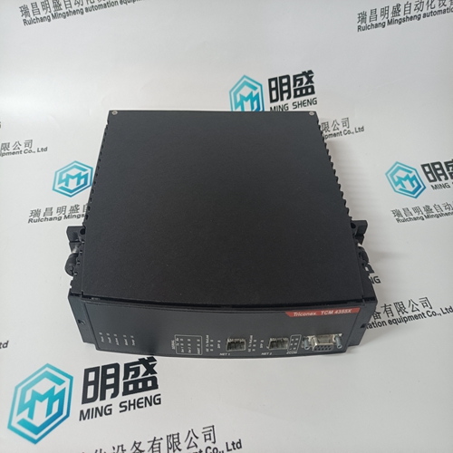
TRICONEX TCM 4355X Pulse input module
- Product ID: TCM 4355X
- Brand: TRICONEX
- Place of origin: The United States
- Goods status: new/used
- Delivery date: stock
- The quality assurance period: 365 days
- Phone/WhatsApp/WeChat:+86 15270269218
- Email:stodcdcs@gmail.com
- Tags:TRICONEXTCM 4355XPulse input module
- Get the latest price:Click to consult
The main products
Spare parts spare parts, the DCS control system of PLC system and the robot system spare parts,
Brand advantage: Allen Bradley, BentlyNevada, ABB, Emerson Ovation, Honeywell DCS, Rockwell ICS Triplex, FOXBORO, Schneider PLC, GE Fanuc, Motorola, HIMA, TRICONEX, Prosoft etc. Various kinds of imported industrial parts
Products are widely used in metallurgy, petroleum, glass, aluminum manufacturing, petrochemical industry, coal mine, papermaking, printing, textile printing and dyeing, machinery, electronics, automobile manufacturing, tobacco, plastics machinery, electric power, water conservancy, water treatment/environmental protection, municipal engineering, boiler heating, energy, power transmission and distribution and so on.
TRICONEX TCM 4355X Pulse input module
There are 3 primary menu lists that organize the access to all of the information that is available on the display. These menu lists are available at all times. The user simply uses the navigation cross to Focus on the desired page and press Enter, or use the the Black ‘soft keys’ (no Focus needed). Run/Operation menus - The HOME page contains the Run/Operation menus and is automatically updated to match the configuration of the control. Service menus - The Service ‘HOME’ page contains navigation buttons to all of the service related parameters and special feature of the control and it too is is automatically updated to match the configuration of the Configuration menus - The Configuration ‘HOME’ page contains navigation buttons to all features and options of the 505. When the unit is in Configure Mode (IOLOCK) the background of all pages will be a blue gradient as shown below, in addition to the status in the upper right.
Exiting the Configure Mode
Once the programming steps have been completed, the Program Mode can be exited. To exit the Configure mode the User Level must still be logged in with Configure privileges. Then the ‘Exit Configuration’ softkey will be available on the MODE screen. Pressing this initiates the 505 to save the configuration and exit IO Lock. If there are no errors in the configuration, the 505 will be in the Shutdown state. At this point it may be ready to reset and run but, if this is the first time the 505 has been configured with the unit’s actuator/linkage/valve, then it is recommended to run the valve stroking procedure in calibration mode and adjust current limits as needed. However, if there is an error in the program, the 505 will be in a shutdown state and unable to reset. Configuration errors can be viewed by going to the Configuration Menu (softkey on the HOME/main menu screen) and pressing the ‘Config Check’ softkey. The next section identifies the various configuration error messages and explains the meaning of the error. There is a procedure in the Appendix on how to restore a unit to the original factory defaults, using a service tool. Configuration Error Messages The control automatically performs a check on the configured values to assure that required program blocks have values loaded into them. This check cannot determine if the values entered are realistic but it makes sure that values have been loaded into required parameters. If any errors are found in the program, the 505 will remain in a shutdown state and a banner message will appear on the Configuration Menu and MODE screens. They can be displayed by pressing the ‘Config Check’ softkey on the Configuration Menu screen. The configuration error message alerts you that a configuration change is required before the 505 can operate the turbine. All errors must be corrected before in order to be able to reset the 505 to the “Ready to Start” condition.
Actuator Driver Limits
To ensure proper control to actuator resolution do not calibrate the span of the actuator output to less than a range of 100 mA (20–160 mA output) or 12 mA (4–20 mA output). If necessary, the actuator to valve linkage may need to be adjusted to ensure proper 505 to valve resolution. Calibration Mode, required to force/stroke the actuator(s), is only available when the 505 control is in a shutdown state. After enabling Calibration Mode, there are options available to adjust the minimum and maximum stops and to manually stroke the output(s). The manual adjustment mode can be used to stroke the actuator and valves from 0 to 100% after the minimum and maximum positions have been adjusted. This allows both the actuator and valve to be tested for binding, play, resolution, linearity, and repeatability. As a safety precaution, if turbine speed ever exceeds either of the speed probe failed speed settings the Calibration mode will be automatically disabled, which disables forcing of the actuator and takes actuator currents to zero.
When adjusting or testing actuator and valve travel, verify that sufficient valve overtravel at the minimum stop is achieved (1%). This assures that each valve can fully close to completely shut off the steam flow to the turbine.
Calibration/Stroking Procedure
Before calibrating or testing, the unit must be tripped and the steam supply removed. This is to ensure that opening the control valve(s) will not allow steam into the turbine. Overspeeding the turbine may cause damage to turbine and can cause severe injury or death to personnel. STEAM TO THE TURBINE MUST BE SHUT OFF BY OTHER MEANS DURING THIS PROCESS. 1. The 505 must be shutdown to enter Calibration Mode. 2. Go to the MODE screen by pressing the MODE key. 3. Enter Calibration Mode by pressing the ‘Calibration’ softkey. The following permissives must be met: a. Unit Shutdown b. No Speed Detected c. Appropriate User Level Login 4. Navigate to the Actuator Driver Summary page by pressing the ‘Drivers’ in either the HOME menu or Configure menu. 5. Select the desired Actuator channel. 6. In the Actuator channel screen, press the ‘Calibration’ softkey to access the calibration options. 7. Press the ‘Force Output’ softkey to access the Actuator Forcing screen. 8. Verify the green “Calmode Enabled” LED is ON to confirm that the unit is in Calibration Mode.al 26839V1 505 Digital Governor for Single/Split-Range Actuators Woodward 135 9. Press the ‘Forcing’ sofkey. Then confirm on the popup that actuator forcing can be enabled by selecting ‘OK’ and pressing ENTER. 10. Verify that the green “Forcing Enabled” LED is now also ON. 11. Use the focus navigation to select and adjust items on the screen (Manual Adjust, Goto Demand, Force Rate, etc.). 12. Actuator current output at min and max can be adjusted by selecting “mA at 0% Demand” or “mA at 100% Demand”. Use the up/down Adjust arrows or numerical keypad and ENTER key to the change the values. 13. Press the ‘Commands’ softkey to access other commands such as “Go to Min”, Go to Max”, and “GO”. “GO” can be used with the “Goto Demand” value.