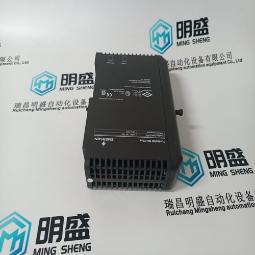
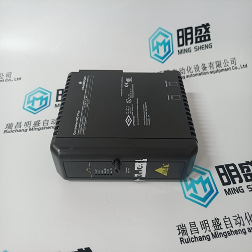
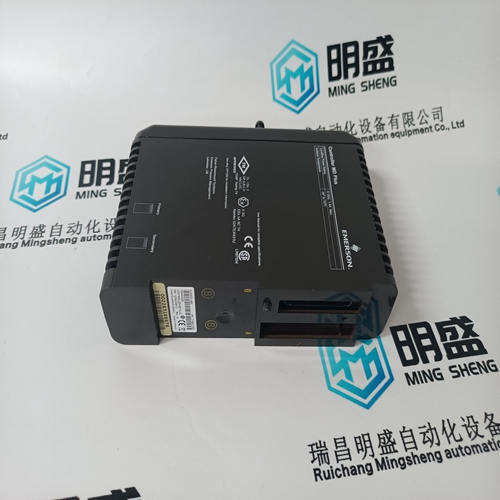
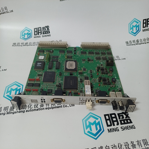
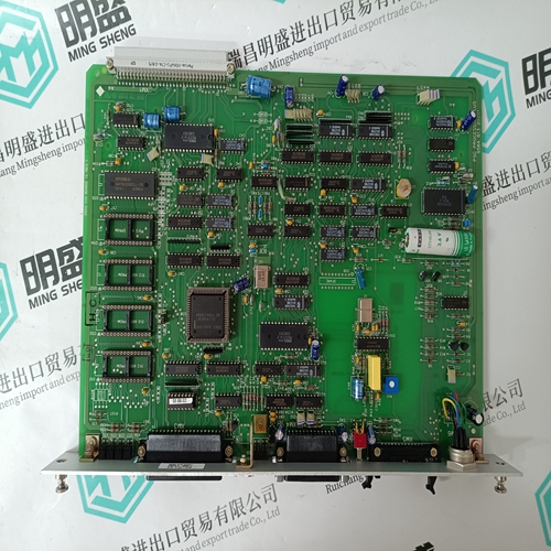
Home > Product > DCS control system > VE3008 12P3439X012 KJ2003X1-BB1 module
VE3008 12P3439X012 KJ2003X1-BB1 module
- Product ID: VE3008 12P3439X012 KJ2003X1-BB1
- Brand: EMERSON
- Place of origin: The United States
- Goods status: new/used
- Delivery date: stock
- The quality assurance period: 365 days
- Phone/WhatsApp/WeChat:+86 15270269218
- Email:stodcdcs@gmail.com
- Tags:VE3008 12P3439X012KJ2003X1-BB1module
- Get the latest price:Click to consult
The main products
Spare parts spare parts, the DCS control system of PLC system and the robot system spare parts,
Brand advantage: Allen Bradley, BentlyNevada, ABB, Emerson Ovation, Honeywell DCS, Rockwell ICS Triplex, FOXBORO, Schneider PLC, GE Fanuc, Motorola, HIMA, TRICONEX, Prosoft etc. Various kinds of imported industrial parts
Products are widely used in metallurgy, petroleum, glass, aluminum manufacturing, petrochemical industry, coal mine, papermaking, printing, textile printing and dyeing, machinery, electronics, automobile manufacturing, tobacco, plastics machinery, electric power, water conservancy, water treatment/environmental protection, municipal engineering, boiler heating, energy, power transmission and distribution and so on.
VE3008 12P3439X012 KJ2003X1-BB1 module
The 505 is a field configurable steam turbine control and graphical user interface (GUI) integrated into one package. The 505 control has been designed to run 2 separate, independent programs on the same platform. One controls the I/O and therefore controls turbine operation. The other program provides all the visual and command interaction with the user.
The primary application program is the GAP based control application program. This controls all the system I/O and functional algorithms which control the operation of the turbine. The secondary application program is the Digia/Qt based graphical user interface (GUI) program. This controls all the screen information that is displayed to the user. It links to the GAP via an internal communication link to pass all required interface variables to and from the display. Both of these programs are automatically launched at power-up. The GAP program MUST always be executing to run the turbine. However the GUI program may be ‘Stopped’ using a service tool (AppManager) and restarted at any time without affecting GAP or the turbine operation. This unique and useful feature of the 505 allows the following operations to be accomplished (if needed or desired) while the 505 control is operating the turbine. Change the language on the screen Update the GUI program (newer build revisions with improvement/enhancements) Upgrade the GUI program – load a custom version that may be created for a specific OEM or customer jobsite
Control Mode Architecture
Basic control program architecture is illustrated in Figure 5-1. The 505’s normal operating architecture divides the control into two states. Run – which includes Operation and Calibration modes Program - Configuration mode Pressing the MODE key at anytime will open the Login and Mode Screen The Configuration Mode is used to configure the 505 for the specific application and set all operating parameters (see Chapter 4). In this mode the control will issue an IOLOCK (LED) and the state of all Outputs from the 505 are disabled. This means that all Relays are de-energized and all Analog/Driver outputs are at zero current. Initially all 505’s must be placed in this mode to enter a valid configuration of the I/O and functions desired for the specific turbine application. The Calibration Mode is used after the configuration of the 505 is complete. It is used to perform calibration of signals, verification of speed signals and the forcing of outputs of the control in preparation to run the turbine. All I/O is functional in this state. To enter this mode the turbine must be TRIPPED (LED). The Operation Mode is used to view operating parameters and run the turbine. This is the typical mode the control uses and is the default mode it enters at Power-up. All I/O is functional in this state. The turbine may be either running or not running in this mode.
Navigation
This is NOT a touchscreen! Due to quality, robustness, screen cleanliness and long term reliability concerns Woodward chose not to implement a touchscreen directly on this product. Using the RemoteView tool a user can take advantage of either a mouse device or a touchscreen on an external computer, but for navigation and selection directly on the 505 display, buttons and an IN-Focus highlighter indication are used. In general the maroon buttons provide navigation from page-to-page and throughout the components on a page. Most of the navigation is done with the Navigation cross.
Any time that a Display application program is not running, the ‘Splash Screen’ will appear. If at power-up the Alarm LED stops flashing and this screen still appears – then the GUI program has not initialized correctly. Once the unit has been configured, all following power cycles will result in a screen similar to the following, dependent on what functionality has been configured.
There is a Screen Saver function that is invoked after a period of inactivity. It is defaulted to 4 hours (adjustable in Service / Screen Settings) – when this comes it a small version of the ‘Splash Screen’ will bounce around on the screen. Press any key to revive the display (maroon keys are recommended). When awaking from screen saver the user login level will be reduced to Operator. This also is adjustable in Service / Screen Settings if desired, it can be changed to awaken to Monitor
