Home > Product > PLC programmable module > MITSUBISHI A1S61PN Power supply module
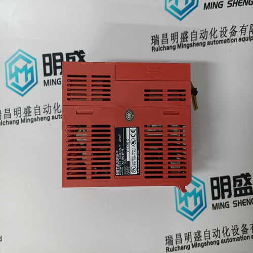
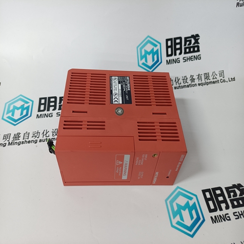
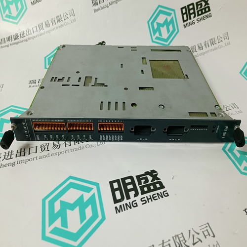
MITSUBISHI A1S61PN Power supply module
- Product ID: A1S61PN
- Brand: MITSUBISHI
- Place of origin: JAPAN
- Goods status: new/used
- Delivery date: stock
- The quality assurance period: 365 days
- Phone/WhatsApp/WeChat:+86 15270269218
- Email:stodcdcs@gmail.com
- Tags:MITSUBISHIA1S61PNPower supply module
- Get the latest price:Click to consult
The main products
Spare parts spare parts, the DCS control system of PLC system and the robot system spare parts,
Brand advantage: Allen Bradley, BentlyNevada, ABB, Emerson Ovation, Honeywell DCS, Rockwell ICS Triplex, FOXBORO, Schneider PLC, GE Fanuc, Motorola, HIMA, TRICONEX, Prosoft etc. Various kinds of imported industrial parts
Products are widely used in metallurgy, petroleum, glass, aluminum manufacturing, petrochemical industry, coal mine, papermaking, printing, textile printing and dyeing, machinery, electronics, automobile manufacturing, tobacco, plastics machinery, electric power, water conservancy, water treatment/environmental protection, municipal engineering, boiler heating, energy, power transmission and distribution and so on.
MITSUBISHI A1S61PN Power supply module
The Auxiliary Control screen will adapt to the configuration of the 505. During normal run operation, this screen provides the user with all details that are related to the auxiliary control loop. The auxiliary control output goes to the LSS bus and can directly affect the HP valve demand output. This can be configured as a limiter or a controller. If it is a limiter it will always be enabled and provide protection related to the process variable being used for this function. When configured as a controller it will disable the speed PID whenever it’s enabled. The menu bar functions will allow the user to access a number of other screens that are related to auxiliary control, such as directly entering a setpoint, access to the valve limiter, or adjusting auxiliary control dynamic settings. The Auxiliary 2 Control is identical to the Auxiliary Control with the exception that it can only be used as a limiter.
The Analog Input Summary screen will display the status of all channels available on the 505 hardware. The fault status, function, device tag, engineering value and units are shown for each channel as well as navigation buttons for each channel that take the user to a page showing all parameters available for that input. The menu bar functions will allow the user to access the detailed page of the speed input signals
Contact Input Summary Screen
The Contact Input Summary screen will display the status of channels available on the 505 hardware. The fault status, function, and device tags are shown for each channel as well as navigation buttons for each channel that take the user to a page showing all parameters available for that input. The contact input summary is broken into 3 pages and the menu bar contains navigation buttons to view all the channels
The Analog Output Summary screen will display the status of all channels available on the 505 hardware. The fault status, function, device tag, engineering value and units are shown for each channel as well as navigation buttons for each channel that take the user to a page showing all parameters available for that output.The Relay Output Summary screen will display the status of all channels available on the 505 hardware. The coil status, function, and device tag are shown for each channel as well as navigation buttons for each channel that take the user to a page showing all parameters available for that output.
Starting Procedures
The Actuator Driver Summary screen will display the status of the 2 channels available on the 505 hardware. The fault status, function, current value (in mA), engineering value and units are shown for each channel as well as navigation buttons for each channel that take the user to a page showing all parameters available for that input.
Refer to the turbine manufacturer’s operating procedures for complete information on turbine start up, and Chapter 3 of this manual for a step by step procedure, depending on the start mode selected. The following is a typical startup procedure:1. Press the RESET key to clear all alarms and trips. If the 505’s RESET CLEARS TRIP setting is programmed "YES", the 505's shutdown relay will reset or energize upon pressing the RESET key after a shutdown. If the RESET CLEARS TRIP OUTPUT setting is programmed "NO", the 505's shutdown relay will reset or energize upon pressing the Reset key ONLY after all trip conditions are cleared. 2. Press the START key and Confirm, to initiate the selected start-up mode. This will function from any screen, but it is recommended to be on the Startup Curve page during the turbine startup. It will automatically be matched to show the correct information relative to the start sequence that has been configured. If a semi-automatic start mode is configured, the valve limiter must be manually increased to open the control valve. A ‘Start Perm Not Closed’ alarm will be issued if the application is using a Start Permissive contact input and this contact input was not closed when the RUN command was issued. 3. After the selected start-up mode has been performed, the turbine will operate at the minimum or idle speed setting. The 505’s speed set point will move to minimum governor speed unless an idle speed is programmed. The Idle/Rated or Auto Start Sequence functions must be programmed for the turbine to control at idle speed. An operator at this time may vary turbine speed through the 505's keypad, external switches or communication links.
