Home > Product > PLC programmable module > MITSUBISHI A1S68DAV Digital output module
MITSUBISHI A1S68DAV Digital output module
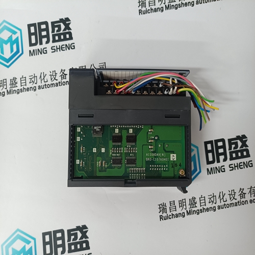
- Product ID: A1S68DAV
- Brand: MITSUBISHI
- Place of origin: JAPAN
- Goods status: new/used
- Delivery date: stock
- The quality assurance period: 365 days
- Phone/WhatsApp/WeChat:+86 15270269218
- Email:stodcdcs@gmail.com
- Tags:MITSUBISHIA1S68DAVDigital output module
- Get the latest price:Click to consult
The main products
Spare parts spare parts, the DCS control system of PLC system and the robot system spare parts,
Brand advantage: Allen Bradley, BentlyNevada, ABB, Emerson Ovation, Honeywell DCS, Rockwell ICS Triplex, FOXBORO, Schneider PLC, GE Fanuc, Motorola, HIMA, TRICONEX, Prosoft etc. Various kinds of imported industrial parts
Products are widely used in metallurgy, petroleum, glass, aluminum manufacturing, petrochemical industry, coal mine, papermaking, printing, textile printing and dyeing, machinery, electronics, automobile manufacturing, tobacco, plastics machinery, electric power, water conservancy, water treatment/environmental protection, municipal engineering, boiler heating, energy, power transmission and distribution and so on.
MITSUBISHI A1S68DAV Digital output module
It is recommended to perform Overspeed Tests from these screens, either at the control (preferred) or via the RemoteView service tool. Alternatively the turbine’s overspeed logic and circuitry can be tested remotely, by programming an Overspeed Test contact input. The Overspeed Test contact functions as the enable external test on the display. When the conditions outlined in the above procedure are met, closing this contact allows the Speed set point to be increased up to the “Overspeed Test limit” setting. The testing procedure is similar to using the OSPD key. An Overspeed Test Enabled relay can be programmed to provide the status feedback that testing is enabled. The Overspeed Test function cannot be performed over the Modbus communications, however, the Overspeed Test Permissive, Overspeed Test In Progress, Overspeed Alarm, and Overspeed Trip indications are available through Modbus.
The STOP key is used to perform a controlled/manual turbine shutdown or stop. To perform a Manual Shutdown, press the STOP key and confirm from the keypad or close the Controlled Shutdown contact input (if programmed) or select Controlled Shutdown from a Modbus communications link. Once initiated, the display dialog box will change to give the user the option to abort the Normal stop sequence. This dialog box will close after 10 seconds, but can be reopened by pressing the STOP key. This function can be also be stopped by opening the contact or selecting Abort Controlled Shutdown from a Modbus communications link.
Alarm Summary
The ALARM screen is always available with the VIEW button under the ALARM LED. When an alarm is detected, it gets latched in the event logic, the Alarm relay is energized, and the ALARM LED illuminates (Yellow). The cause of the event will be indicated with an Event ID, description and time/date stamp on the Alarm Summary page. The list will always place the first event at the top of the list, if more than one alarm condition is present they will all be listed with their corresponding time stamp. To clear any alarms that are no longer present, press the RESET key, close the Reset contact input, or select Reset from either Modbus communications link. If the cause of the event has been corrected the alarm will clear, it not it will remain and the time-stamp will remain unchanged.
Each individual alarm condition is available through the Modbus links to monitor the control status. A common alarm indication is also provided. Relay indications can be programmed to indicate a 505 Common Alarm, in addition to the dedicated Alarm Relay output. The table below lists all the potential alarm conditions and their Event ID.
Shutdown Summary
The Shutdown Summary screen is always available with the VIEW button under the TRIPPED LED. When a trip is detected, it gets latched in the event logic, the Trip relay is de-energized, all steam valve demand outputs go to zero, and the TRIPPED LED illuminates (Red). The cause of the event will be indicated with an Event ID, description and time/date stamp on the Shutdown Summary page. The list will always place the first event at the top of the list, if more than one trip condition is present they will all be listed with their corresponding time stamp. To clear any shutdowns that are no longer present, press the RESET key, close the Reset contact input, or select Reset from either Modbus communications link. If the cause of the event has been corrected the event will clear, it not it will remain and the time-stamp will remain unchanged.
Each individual trip condition is available through the Modbus links to monitor the control status. A common trip indication is also provided. Relay indications can be programmed to indicate a 505 Shutdown Condition (energizes for a shutdown condition) or a Trip Relay (de-energizes for a shutdown/trip), in addition to the dedicated Emergency Trip Relay output.