Home > Product > DCS control system > REF615C_E HCFDACADABC2BAN11E control panel
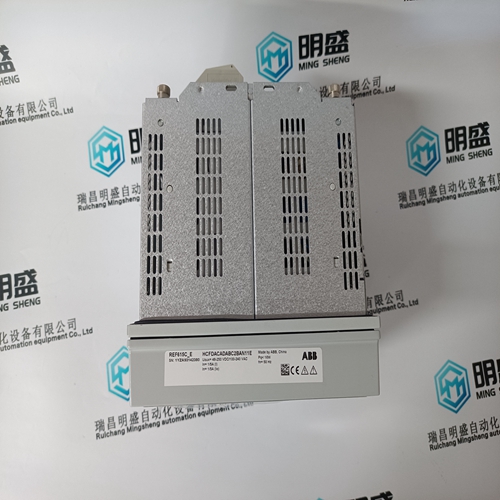
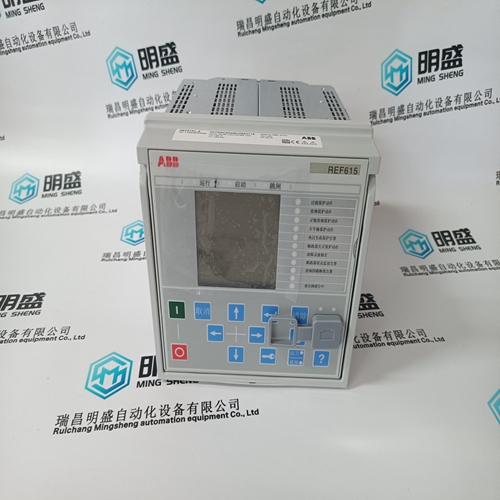
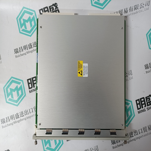
REF615C_E HCFDACADABC2BAN11E control panel
- Product ID: REF615C_E HCFDACADABC2BAN11E
- Brand: ABB
- Place of origin: The Swiss
- Goods status: new/used
- Delivery date: stock
- The quality assurance period: 365 days
- Phone/WhatsApp/WeChat:+86 15270269218
- Email:stodcdcs@gmail.com
- Tags:REF615C_E HCFDACADABC2BAN11Econtrol panel
- Get the latest price:Click to consult
The main products
Spare parts spare parts, the DCS control system of PLC system and the robot system spare parts,
Brand advantage: Allen Bradley, BentlyNevada, ABB, Emerson Ovation, Honeywell DCS, Rockwell ICS Triplex, FOXBORO, Schneider PLC, GE Fanuc, Motorola, HIMA, TRICONEX, Prosoft etc. Various kinds of imported industrial parts
Products are widely used in metallurgy, petroleum, glass, aluminum manufacturing, petrochemical industry, coal mine, papermaking, printing, textile printing and dyeing, machinery, electronics, automobile manufacturing, tobacco, plastics machinery, electric power, water conservancy, water treatment/environmental protection, municipal engineering, boiler heating, energy, power transmission and distribution and so on.
REF615C_E HCFDACADABC2BAN11E control panel
The Speed, Cascade, Auxiliary and Auxiliary 2 controls are PID controllers. The response of each control loop can be adjusted by selecting the dynamics mode as described above. Proportional gain, integral gain (stability), and DR (derivative ratio) are the adjustable and interacting parameters used to match the response of the control loop with the response of the system. They correspond to the P (proportional), I (integral), and D (derivative) terms, and are displayed by the 505 as follows: P = Proportional gain (%) I = Integral gain (%) D = Derivative (determined by DR and I) Tuning P & I Gains Proportional gain must be tuned to best respond to a system transient or step change. If system response is not known, a typical starting value is 5%. If proportional gain is set too high the control will appear to be overly sensitive, and may oscillate with a cycle time of less than 1 second. Integral gain must be tuned gain for best control at steady state. If system response is not known a typical starting value is 5%. If the integral gain is set too high the control may hunt or oscillate at cycles times of over 1 second.
For best response the proportional gain
and integral gain should be as high as possible. To obtain a faster transient response, slowly increase the proportional gain setting until the actuator or final driver output begins to oscillate or waver. Then adjust the integral gain as necessary to stabilize the output. If stability cannot be obtained with the integral gain adjustment, reduce the proportional gain setting. A well tuned system, when given a step change, should slightly overshoot the control point then come into control. A PID control loop’s gain is a combination of all the gains in the loop. The loop’s total gain includes actuator gain, valve gain, and valve linkage gain, transducer gain, internal turbine gains, and the 505’s adjustable gains. If the accumulated mechanical gain (actuators, valves, valve linkage, etc.) is very high, the 505’s gain must be very low to be added to the system gain required for system stability. In cases where a small change in the 505's output results in a large speed or load change (high mechanical gain) it may not be possible to take the 505's gains low enough to reach stable operation. In those cases the mechanical interface (actuator, linkage, servo, valve rack) design and/or calibration should be reviewed and changed to achieve a gain of one where 0–100% 505 output corresponds to 0–100% valve travel.
Dual Dynamics (Speed/Load)
The Speed PID has two sets of dynamics, On-Line and Off-Line; each include Proportional Gain, Integral Gain, and Derivative Ratio (DR) variables. There are three cases that determine when the dynamics switch between On-Line and OffLine: A “Select On-Line Dynamics” contact input is programmed Unit is driving a generator Unit is driving a mechanical drive (not a generator) If a contact input is programmed to “Select On-Line Dynamics”, it has priority regardless of the driven device. When the contact is closed, On-Line dynamics are selected; when open, Off-Line dynamics are selected. If the unit is driving a generator and no “Select On-Line Dynamics” contact input is programmed, the Speed Off-Line dynamics are used by the Speed PID when the generator or utility tie breaker contacts are open. The speed On-Line dynamics are used by the speed PID when the generator and utility tie breaker contacts are closed. If the speed dynamics select contact is programmed, the generator and utility tie contacts do not effect the dynamics selection. If the unit is not driving a generator and no “Select On-Line Dynamics” contact input is programmed, the Speed Off-Line dynamic settings are used when the turbine speed is below minimum governor speed; .On-Line dynamics are used if the turbine speed is above minimum governor speed. If the speed dynamics select contact is programmed, the turbine speed does not effect the dynamics selection. A relay can be programmed to indicate that the On-Line Dynamics mode is selected.