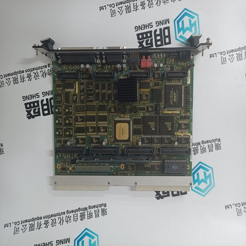
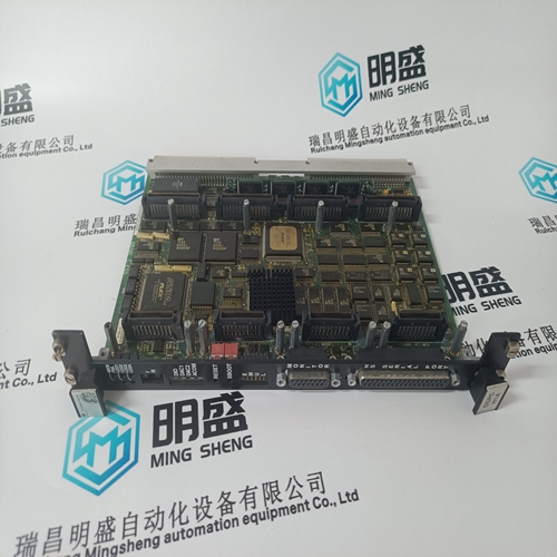
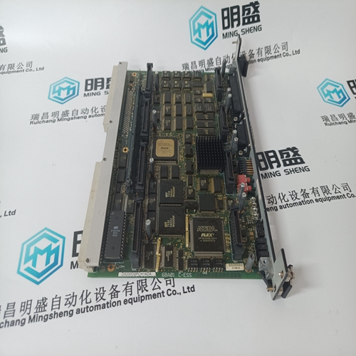
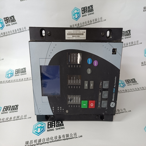
Home > Product > Gas turbine system > DS200DSPCH1ADA combustion engine card
DS200DSPCH1ADA combustion engine card
- Product ID: DS200DSPCH1ADA
- Brand: GE
- Place of origin: the United States
- Goods status: new/used
- Delivery date: stock
- The quality assurance period: 365 days
- Phone/WhatsApp/WeChat:+86 15270269218
- Email:stodcdcs@gmail.com
- Tags:DS200DSPCH1ADAcombustion engine card
- Get the latest price:Click to consult
The main products
Spare parts spare parts, the DCS control system of PLC system and the robot system spare parts,
Brand advantage: Allen Bradley, BentlyNevada, ABB, Emerson Ovation, Honeywell DCS, Rockwell ICS Triplex, FOXBORO, Schneider PLC, GE Fanuc, Motorola, HIMA, TRICONEX, Prosoft etc. Various kinds of imported industrial parts
Products are widely used in metallurgy, petroleum, glass, aluminum manufacturing, petrochemical industry, coal mine, papermaking, printing, textile printing and dyeing, machinery, electronics, automobile manufacturing, tobacco, plastics machinery, electric power, water conservancy, water treatment/environmental protection, municipal engineering, boiler heating, energy, power transmission and distribution and so on.
DS200DSPCH1ADA combustion engine card
The 505 control is programmed to function as a slave unit only. As a slave unit, the 505 will only respond to a transaction request by a master device. The 505 can directly communicate with a DCS or other Modbus supporting device on a single communications link, or through a multi-dropped network. If multi-dropping is used, up to 246 devices (505s or other customer devices) can be connected to one Master device on a single network. The control address is programmed under the 505’s communications block and can be changed in the service mode, if needed.
Each message to or from a master has a defined structure called the message “frame”. A frame consists of the slave device address, a code defining the requested data, and error checking information. See Figure 6-2.The Modbus function code tells the addressed slaves what function to perform. The following table lists the function codes supported by this control.
Modbus Function Codes
When a Modbus message is received, it is checked for any errors or invalid data. If there is invalid data in the message, an error code is sent back to the master and the control issues an alarm message. The error codes are defined in the following table. The exception error status and respective error codes can be viewed on the Communication pages under the Service Menu. If the control has not received a message for the configured time-out period, the control will alarm with an error message, but no message is sent to the master. This time-out is defaulted to 2 seconds and only applies to units using both monitor and control (adjustable through the Service Menu).
Holding coils are logical signals that are both readable from and writable to the 505 control. An example of a Boolean write value would be raise or lower commands. A logical true denoted by the value 1 will cause the command listed in the description to be executed. For example, if a 1 is written to address 0:0010 and this corresponded to a speed raise command, the manual speed set point will increase until a 0 is written to address 0:0010. The 505 control supports function codes 1, 5, and 15. These correspond to reading selected holding coils, writing to a single holding coil, and writing to multiple holding coils, respectively. The holding coils available are listed in Table 6-5.
505 Control Modbus Addresses
The Modbus communication ports in the 505 control are programmed for unique Modbus addresses. A complete listing of these addresses for your application is located at the end of this section in the manual. The Modbus address listing consists of Boolean Writes, Boolean Reads, Analog Reads, and Analog Writes. The Boolean reads and writes are also referred to as input and holding coils. The analog reads and writes are also referred to as input registers and holding registers. All values that can be addressed by Modbus are considered to be discrete and numeric. The discrete values are a 1 bit binary, on or off value and the numerics are 16 bit values. Discrete values are sometimes referred to as coils or digitals and numerics are referred to as registers or analogs. All read/write registers are interpreted by the 505 as signed 16 bit integer values. Since Modbus can only handle integers, values that require a decimal point in the Modbus Master Device are multiplied by a scaling constant before being sent by 505. See Tables 6-7 and 6-8 for defaulted communication constants and ranges. The maximum number of discretes and registers that can be transmitted in one packet is dependent on each implementation of Modbus. The following table defines these limits.
