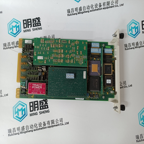
Home > Product > Gas turbine system > IS215UCVEM01A IS215UCVEH2AF Gas turbine card
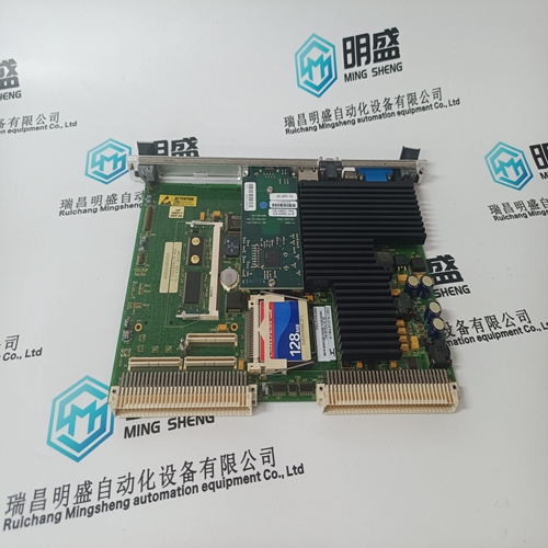
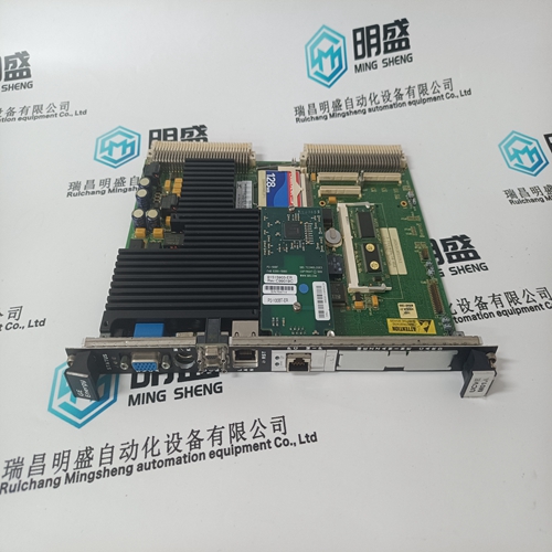
IS215UCVEM01A IS215UCVEH2AF Gas turbine card
- Product ID: IS215UCVEM01A IS215UCVEH2AF
- Brand: GE
- Place of origin: the United States
- Goods status: new/used
- Delivery date: stock
- The quality assurance period: 365 days
- Phone/WhatsApp/WeChat:+86 15270269218
- Email:stodcdcs@gmail.com
- Tags:IS215UCVEM01A IS215UCVEH2AFGas turbine card
- Get the latest price:Click to consult
The main products
Spare parts spare parts, the DCS control system of PLC system and the robot system spare parts,
Brand advantage: Allen Bradley, BentlyNevada, ABB, Emerson Ovation, Honeywell DCS, Rockwell ICS Triplex, FOXBORO, Schneider PLC, GE Fanuc, Motorola, HIMA, TRICONEX, Prosoft etc. Various kinds of imported industrial parts
Products are widely used in metallurgy, petroleum, glass, aluminum manufacturing, petrochemical industry, coal mine, papermaking, printing, textile printing and dyeing, machinery, electronics, automobile manufacturing, tobacco, plastics machinery, electric power, water conservancy, water treatment/environmental protection, municipal engineering, boiler heating, energy, power transmission and distribution and so on.
IS215UCVEM01A IS215UCVEH2AF Gas turbine card
Boolean Reads (Input Coils) Input coils are logical signals that are readable from, but not writable to, the 505 control. An example of an Boolean read value would be a turbine trip status indication. The input coil will have the value 1 if the statement in the description column is true and a 0 if false. The `1:’ term in the address identifies an input coil. The 505 control supports Modbus function code 2, which involves reading selected input coils. The input coils available are listed in Table 6-6. Analog Reads (Input Registers) Input registers are analog values that are readable from, but not writable to, the 505 control. An example of an analog read value would be turbine speed. The values of the input registers are stored internal to the control as floating point numbers representing engineering units (kPa or rpm). The values that are transmitted are integer values ranging from -32767 to +32767. Since Modbus can only handle integers, values that have a decimal point are multiplied by a constant before being sent by Modbus. For example, these input registers may be listed as the Modbus value `x100’ or `x10’ under the description heading to denote the value is multiplied by a scaling constant. This will allow transmission of decimal parts of a unit if this is necessary for better resolution. See the 505 Service mode for defaulted communication constants and ranges. The 505 control supports Modbus function code 4, which involves reading selected input registers. The input registers available are listed in Table 6-7.
Analog Writes (Holding Registers)
Holding registers are analog values that are writable to the 505 control. These values can also be read from by a device performing error checking. An example of an analog write value would be a direct speed set point value as opposed to raise and lower commands. The value of the holding registers are also stored in the control as numbers representing engineering units (psi or rpm). The 505 control supports Modbus function codes 3, 6, and 16. These correspond to reading selected holding registers, writing to a single holding register, and writing to multiple holding registers, respectively. The holding registers available are listed in Table 6-8. The following tables give the address and description of all Boolean and analog,The controlling parameter status of the 505 uses an Analog Read register (3:0001) to identify the parameters that are in control. This variable follows what is displayed on the controlling parameter screen, under the ‘CONT’ key. The variable gives the current status of the control and is defined in the following table.
Modbus Scale Factors
Modbus has two limitations: only integers can be sent across the value is limited between -32767 and 32767 These limitations can be overcome by scaling the value before it is sent across the Modbus. The default scale factor for the analog values is 1. The scale factor can be changed in the service mode between 1 and 100. The following input and set point values that are sent across the Modbus have independent scale factors: Casc (3:0030), Aux (3:0037), Inlet Steam Pressure (3:0041), Exhaust Steam Pressure (3:0179) KW (3:0045), and Sync/Load Share (3:0043). These scaled parameters and their scale factor are available through the Modbus. Values that require a decimal point must be multiplied by the scale factor (10 or 100) prior to being sent across the Modbus. The value sent must then be divided by the scale factor in the Master. The Scale Factor adjusts all associated analog reads and writes accordingly. For example, the Cascade Scale Factor adjusts the cascade input and set point analog read values as well as the Entered Setpt analog write value. For example, if the Cascade set point of 60.15 needs to be sent across the Modbus and have two decimal places, the Cascade Scale Factor would be set to 100 in the Service Mode. This will change the value so that the decimal places can be sent across the Modbus communications link (60.15 * 100 = 6015). After the value is sent across the Modbus, it must be rescaled in the Master to the original value (6015/100 = 60.15). A Directly Entered Cascade Set Point (4:0002) of 61.5 would be sent across the link as 6150 and the 505 automatically divides the value by the Casc Scale Factor and uses the value of 61.5 as the set point desired.
