Home > Product > PLC programmable module > ICS TRIPLEX T8403CX Digital input module
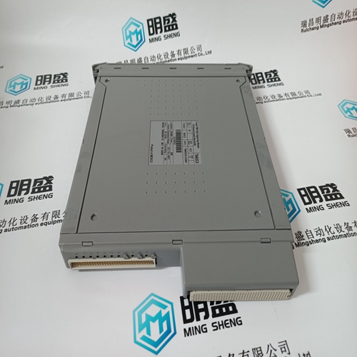
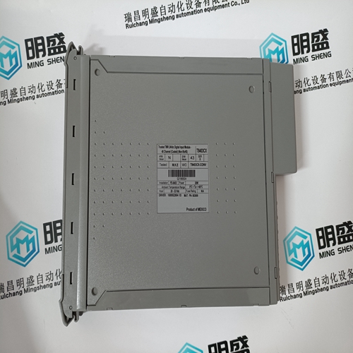
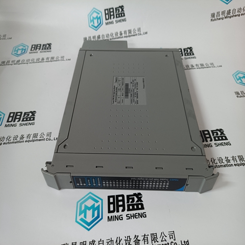
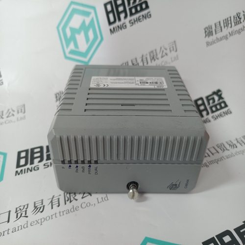
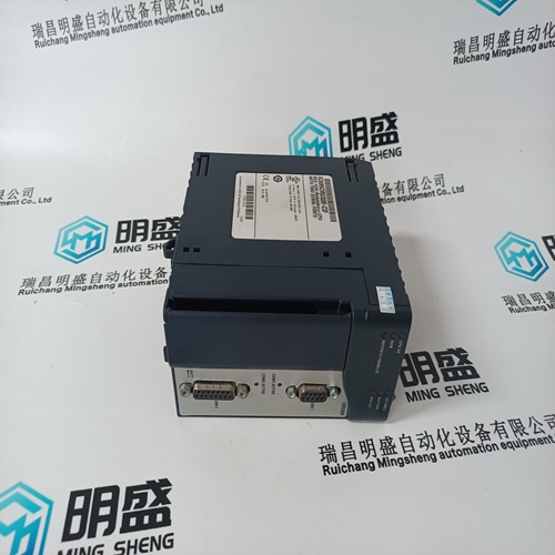
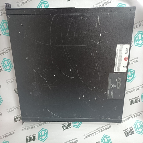
ICS TRIPLEX T8403CX Digital input module
- Product ID: T8403CX
- Brand: ICS TRIPLEX
- Place of origin: the United States
- Goods status: new/used
- Delivery date: stock
- The quality assurance period: 365 days
- Phone/WhatsApp/WeChat:+86 15270269218
- Email:stodcdcs@gmail.com
- Tags:ICS TRIPLEXT8403CXDigital input module
- Get the latest price:Click to consult
The main products
Spare parts spare parts, the DCS control system of PLC system and the robot system spare parts,
Brand advantage: Allen Bradley, BentlyNevada, ABB, Emerson Ovation, Honeywell DCS, Rockwell ICS Triplex, FOXBORO, Schneider PLC, GE Fanuc, Motorola, HIMA, TRICONEX, Prosoft etc. Various kinds of imported industrial parts
Products are widely used in metallurgy, petroleum, glass, aluminum manufacturing, petrochemical industry, coal mine, papermaking, printing, textile printing and dyeing, machinery, electronics, automobile manufacturing, tobacco, plastics machinery, electric power, water conservancy, water treatment/environmental protection, municipal engineering, boiler heating, energy, power transmission and distribution and so on.
ICS TRIPLEX T8403CX Digital input module
This part describes the units and components of the FANUC servo amplifier α series. It also explains the following information necessary to start up the control motor amplifier: • Connecting the power • Setting the printed-circuit board • Initializing the parameter • Confirmation of the operation Make sure that the specifications of the CNC, servo motors, servo amplifiers, and other units you received are exactly what you ordered, and these units are connected correctly. Then, turn on the power. (1) Before turning on the circuit breaker, check the power supply voltage connected. → See Section 3.2. (2) Some types of PSM, SVM, and SPM require settings before the system can be used. So check whether you must make settings. → See Section 3.3. (3) Turn on the power, and set initial parameters on the CNC. For the initialization of servo parameters, refer to the following manual: FANUC AC SERVO MOTOR α series Parameter Manual (B-65150E) For the initialization of spindle parameters, refer to the following manual: FANUC AD SPINDLE MOTOR α series Parameter Manual (B-65160E) (4) For start-up adjustment and troubleshooting, see Chapter 4. • Method of using optional wiring boards for adjustment of the PSM, SVM, and SPM • Spindle sensor adjustment values
VRDY-OFF Alarm Indicated on the CNC Screen
When the VRDY-OFF alarm is indicated on the CNC, check the items listed below. In addition to these causes, there are other possible causes of VRDY-OFF. If the problem still exists after the following items are checked, contact your FANUC service representative. (1) Interface between modules (a) Is a terminating dummy connector for the interface between modules (JX1A, JX1B) attached to JX1B of the module (an SVM or SPM) at the end of the connection chain? (2) Emergency stop signal (ESP) (a) Has the emergency stop signal (connector: CX4) applied to the PSM been released? Alternatively, is the signal connected correctly? (b) Is the emergency stop signal line (pin 3 of connectors CX2A and CX2B) between the PSM and SVM or SPM connected correctly? (3) MCON signal (a) Has the ready command signal MCON been sent from the CNC to SVM? • Check for poor contact in the command cable between the CNC and SVM. • Use the servo check pin board to check the signal level. (b) For the multi-axis amplifier, is the MCON signal sent to all axes? (4) External MCC (a) Is the external MCC connected correctly and is there any problem in the external MCC itself? (5) Timing of turning on the power to the CNC (200 VAC, single phase) and the PSM control power (200 VAC, single phase) (a) Was the power to the CNC turned on at the same time when, or after, the power for PSM control was turned on?
Servo Check Board
The servo check board receives the digital value used for control inside the digital servo as numerical data and converts it to an analog form. For details on how to connect and use the servo check board, refer to the following: FANUC AC SERVO MOTOR α series Parameter Manual B65150E/04 or later editions
(1) The spindle vibrates only when the spindle speed has reached or is at a particular speed level. Check whether the spindle also vibrates when the motor is turning by inertia. If noise is unchanged, investigate the source of mechanical vibration. There are several methods to turn the spindle by inertia as explained below. Because these methods involve machine sequences, consult with the machine tool builder. A. Setting spindle control signal MPOF (FS16 for the first spindle: G73#2, FS15 for the first spindle: G228#2) to 1 immediately causes the spindle to turn by inertia. B. Set ALSP (FS16: bit 2 of parameter No. 4009, FS15 for the first spindle: bit 2 of parameter No. 3009) to 1. Then, when the power to the CNC is turned off during spindle rotation, the spindle turns by inertia. (On the spindle amplifier module, alarm 24 is indicated.) (2) When noise is generated at the time the motor is stopped or at any time A. See Subsection 4.3.4 of this part, and check and adjust the waveform of the spindle sensor. B. Check that the motor part number matches its parameters. For details, refer to "FANUC AC SPINDLE MOTOR α series Parameter Manual." C. Adjust the velocity loop gain and so forth. For details, refer to "FANUC AC SPINDLE MOTOR α series Parameter Manual."