Home > Product > DCS control system > UAD155A0111 3BHE029110R0111 Excitation control card
UAD155A0111 3BHE029110R0111 Excitation control card
- Product ID: UAD155A0111 3BHE029110R0111
- Brand: ABB
- Place of origin: The Swiss
- Goods status: new/used
- Delivery date: stock
- The quality assurance period: 365 days
- Phone/WhatsApp/WeChat:+86 15270269218
- Email:stodcdcs@gmail.com
- Tags:UAD155A0111 3BHE029110R0111Excitation control card
- Get the latest price:Click to consult
The main products
Spare parts spare parts, the DCS control system of PLC system and the robot system spare parts,
Brand advantage: Allen Bradley, BentlyNevada, ABB, Emerson Ovation, Honeywell DCS, Rockwell ICS Triplex, FOXBORO, Schneider PLC, GE Fanuc, Motorola, HIMA, TRICONEX, Prosoft etc. Various kinds of imported industrial parts
Products are widely used in metallurgy, petroleum, glass, aluminum manufacturing, petrochemical industry, coal mine, papermaking, printing, textile printing and dyeing, machinery, electronics, automobile manufacturing, tobacco, plastics machinery, electric power, water conservancy, water treatment/environmental protection, municipal engineering, boiler heating, energy, power transmission and distribution and so on.
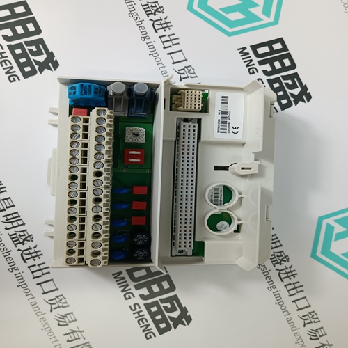
UAD155A0111 3BHE029110R0111 Excitation control card
The 369 is contained in a compact plastic housing with the keypad, display, communication port, and indicators/targets on the front panel. The unit should be positioned so the display and keypad are accessible. To mount the relay, make cutout and drill mounting holes as shown below. Mounting hardware (bolts and washers) is provided with the relay. Although the relay is internally shielded to minimize noise pickup and interference, it should be mounted away from high current conductors or sources of strong magnetic fields.
The 369 can be connected to cover a broad range of applications and wiring will vary depending upon the user’s protection scheme. This section will cover most of the typical 369 interconnections. In this section, the terminals have been logically grouped together for explanatory purposes. A typical wiring diagram for the 369 is shown above in Figure 3–4: TYPICAL WIRING on page 3–6 and the terminal arrangement has been detailed in Figure 3–3: TERMINAL LAYOUT on page 3–5. For further information on applications not covered here, refer to Chapter 7: APPLICATIONS or contact the factory for further information.
369 POWER SUPPLY RANGES
The 369 has a built-in switchmode supply. It can operate with either AC or DC voltage applied to it. Extensive filtering and transient protection has been incorporated into the 369 to ensure reliable operation in harsh industrial environments. Transient energy is removed from the relay and conducted to ground via the ground terminal. This terminal must be connected to the cubicle ground bus using a 10 AWG wire or a ground braid. Do not daisy-chain grounds with other relays or devices. Each should have its own connection to the ground bus.
The 369 requires one CT for each of the three motor phase currents to be input into the relay. There are no internal ground connections for the CT inputs. Refer to Chapter 7: APPLICATIONS for a information on two CT connections. The phase CTs should be chosen such that the FLA of the motor being protected is no less than 50% of the rated CT primary. Ideally, to ensure maximum accuracy and resolution, the CTs should be chosen such that the FLA is 100% of CT primary or slightly less. The maximum CT primary is 5000 A. The 369 will measure 0.05 to 20 × CT primary rated current. The CTs chosen must be capable of driving the 369 burden (see specifications) during normal and fault conditions to ensure correct operation. See Section 7.4: CT SPECIFICATION AND SELECTION on page 7–7 for information on calculating total burden and CT rating.
GROUND CURRENT INPUTS
The 369 has an isolating transformer with separate 1 A, 5 A, and sensitive HGF (50:0.025) ground terminals. Only one ground terminal type can be used at a time. There are no internal ground connections on the ground current inputs. The maximum ground CT primary for the 1 A and 5 A taps is 5000 A. Alternatively the sensitive ground input, 50:0.025, can be used to detect ground current on high resistance grounded systems. The ground CT connection can either be a zero sequence (core balance) installation or a residual connection. Note that only 1 A and 5 A secondary CTs may be used for the residual connection. A typical residual connection is illustrated in below. The zero-sequence connection is shown in the typical wiring diagram. The zero-sequence connection is recommended. Unequal saturation of CTs, CT mismatch, size and location of motor, resistance of the power system, motor core saturation density, etc. may cause false readings in the residually connected ground fault circuit.