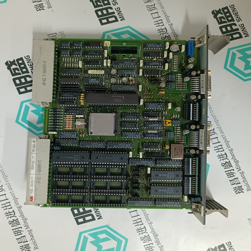
Home > Product > Robot control system > ALSTOM 43297029 Distributed control card
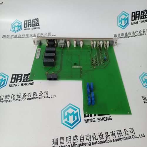
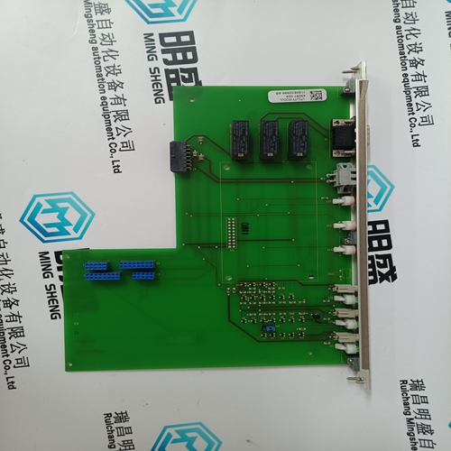
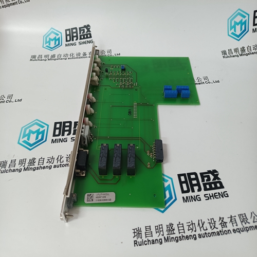
ALSTOM 43297029 Distributed control card
- Product ID: 43297029
- Brand: ALSTOM
- Place of origin: the United States
- Goods status: new/used
- Delivery date: stock
- The quality assurance period: 365 days
- Phone/WhatsApp/WeChat:+86 15270269218
- Email:stodcdcs@gmail.com
- Tags:ALSTOM 43297029Distributed control card
- Get the latest price:Click to consult
The main products
Spare parts spare parts, the DCS control system of PLC system and the robot system spare parts,
Brand advantage: Allen Bradley, BentlyNevada, ABB, Emerson Ovation, Honeywell DCS, Rockwell ICS Triplex, FOXBORO, Schneider PLC, GE Fanuc, Motorola, HIMA, TRICONEX, Prosoft etc. Various kinds of imported industrial parts
Products are widely used in metallurgy, petroleum, glass, aluminum manufacturing, petrochemical industry, coal mine, papermaking, printing, textile printing and dyeing, machinery, electronics, automobile manufacturing, tobacco, plastics machinery, electric power, water conservancy, water treatment/environmental protection, municipal engineering, boiler heating, energy, power transmission and distribution and so on.
ALSTOM 43297029 Distributed control card
The exact placement of a zero sequence CT to properly detect ground fault current is shown below. If the CT is placed over a shielded cable, capacitive coupling of phase current into the cable shield during motor starts may be detected as ground current unless the shield wire is also passed through the CT window. Twisted pair cabling on the zero sequence CT is recommended.
The 369 has three channels for AC voltage inputs each with an internal isolating transformer. There are no internal fuses or ground connections on these inputs. The maximum VT ratio is 240:1. These inputs are only enabled when the metering option (M) is ordered. The 369 accepts either open delta or wye connected VTs (see Figure 3–7: WYE/DELTA CONNECTION below). The voltage channels are connected wye internally, which means that the jumper shown on the delta connection between the phase B input and the VT neutral terminals must be installed. Polarity and phase sequence for the VTs is critical for correct power and rotation measurement and should be verified before starting the motor. As long as the polarity markings on the primary and secondary windings of the VT are aligned, there is no phase shift. The markings can be aligned on either side of the VT. VTs are typically mounted upstream of the motor breaker or contactor. Typically, a 1 A fuse is used to protect the voltage inputs
The Backspin voltage input
is only operational if the optional backspin detection (B) feature has been purchased for the relay. This input allows the 369 to sense whether the motor is spinning after the primary power has been removed (breaker or contactor opened). These inputs must be supplied by a separate VT mounted downstream (motor side) of the breaker or contactor. The correct wiring is illustrated below.The 369 can monitor up to 12 RTD inputs for Stator, Bearing, Ambient, or Other temperature applications. The type of each RTD is field programmable as: 100 Ω Platinum (DIN 43760), 100 Ω Nickel, 120 Ω Nickel, or 10 Ω Copper. RTDs must be the three wire type. There are no provisions for the connection of thermistors. The 369 RTD circuitry compensates for lead resistance, provided that each of the three leads is the same length. Lead resistance should not exceed 25 Ω per lead for platinum and nickel type RTDs or 3 Ω per lead for Copper type RTDs. Shielded cable should be used to prevent noise pickup in industrial environments. RTD cables should be kept close to grounded metal casings and avoid areas of high electromagnetic or radio interference. RTD leads should not be run adjacent to or in the same conduit as high current carrying wires. The shield connection terminal of the RTD is grounded in the 369 and should not be connected to ground at the motor or anywhere else to prevent noise pickup from circulating currents. If 10 Ω Copper RTDs are used special care should be taken to keep the lead resistance as low as possible to maintain accurate readings.
ANALOG OUTPUTS
The 369 provides 1 analog current output channel as part of the base unit and 3 additional analog outputs with the metering option (M). These outputs are field programmable to a full-scale range of either 0 to 1 mA (into a maximum 2.4 kΩ impedance) and 4 to 20 mA or 0 to 20 mA (into a maximum 600 Ω impedance). As shown in the typical wiring diagram (Figure 3–4: TYPICAL WIRING on page 3–6), these outputs share one common return. Polarity of these outputs must be observed for proper operation. Shielded cable should be used for connections, with only one end of the shield grounded, to minimize noise effects. The analog output circuitry is isolated. Transorbs limit this isolation to ±36 V with respect to the 369 safety ground. If an analog voltage output is required, a burden resistor must be connected across the input of the SCADA or measuring device (see the figure below). Ignoring the input impedance of the input,
Other than the ACCESS switch input the other 5 digital inputs are programmable. These programmable digital inputs have default settings to match the functions of the 269Plus switch inputs (differential, speed, emergency restart, remote reset and spare). However in addition to their default settings they can also be programmed for use as generic inputs to set up trips and alarms or for monitoring purposes based on external contact inputs. A twisted pair of wires should be used for digital input connections.
