Home > Product > Robot control system > ALSTOM BGTR8HE 24491276A1004 framework
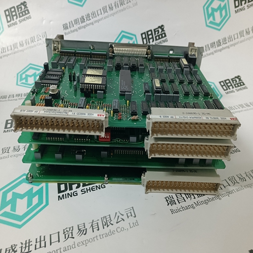
ALSTOM BGTR8HE 24491276A1004 framework
- Product ID: BGTR8HE 24491276A1004
- Brand: ALSTOM
- Place of origin: the United States
- Goods status: new/used
- Delivery date: stock
- The quality assurance period: 365 days
- Phone/WhatsApp/WeChat:+86 15270269218
- Email:stodcdcs@gmail.com
- Tags:ALSTOMBGTR8HE 24491276A1004framework
- Get the latest price:Click to consult
The main products
Spare parts spare parts, the DCS control system of PLC system and the robot system spare parts,
Brand advantage: Allen Bradley, BentlyNevada, ABB, Emerson Ovation, Honeywell DCS, Rockwell ICS Triplex, FOXBORO, Schneider PLC, GE Fanuc, Motorola, HIMA, TRICONEX, Prosoft etc. Various kinds of imported industrial parts
Products are widely used in metallurgy, petroleum, glass, aluminum manufacturing, petrochemical industry, coal mine, papermaking, printing, textile printing and dyeing, machinery, electronics, automobile manufacturing, tobacco, plastics machinery, electric power, water conservancy, water treatment/environmental protection, municipal engineering, boiler heating, energy, power transmission and distribution and so on.
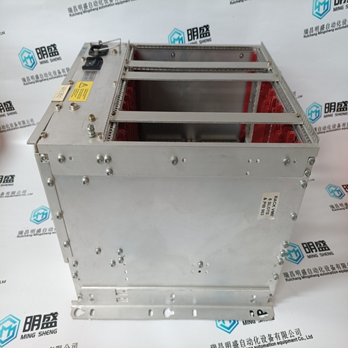
ALSTOM BGTR8HE 24491276A1004 framework
The 369 display can be separated and mounted remotely up to 15 feet away from the main relay. No separate source of control power is required for the display module. A 15 feet standard shielded network cable is used to make the connection between the display module and the main relay. A recommended and tested cable is available from GE Power Management. The cable should be wired as far away as possible from high current or voltage carrying cables or other sources of electrical noise. In addition the display module must be grounded if mounted remotely. A ground screw is provided on the back of the display module to facilitate this. A 12 AWG wire is recommended and should be connected to the same ground bus as the main relay unit. The 369 relay will still function and protect the motor without the display connected.
The 369 provides four (4) form C output relays. They are labeled Trip, Aux 1, Aux 2, and Alarm. Each relay has normally open (NO) and normally closed (NC) contacts and can switch up to 8 A at either 250 V AC or 30 V DC with a resistive load. The NO or NC state is determined by the ‘no power’ state of the relay outputs. All four output relays may be programmed for fail-safe or non-fail-safe operation. When in fail-safe mode, output relay activation or a loss of control power will cause the contacts to go to their power down state. For example: • A fail-safe NO contact closes when the 369 is powered up (if no prior unreset trip conditions) and will open when activated (tripped) or when the 369 loses control power. • A non-fail-safe NO contact remains open when the 369 is powered up (unless a prior unreset trip condition) and will close only when activated (tripped). If control power is lost while the output relay is activated (NO contacts closed) the NO contacts will open.

Thus, in order to cause a trip on loss of control power to the 369
the Trip relay should be programmed as fail-safe. See the figure below for typical wiring of contactors and breakers for fail-safe and non-fail-safe operation. Output relays remain latched after activation if the fault condition persists or the protection element has been programmed as latched. This means that once this relay has been activated it remains in the active state until the 369 is manually reset. The Trip relay cannot be reset if a timed lockout is in effect. Lockout time will be adhered to regardless of whether control power is present or not. The relay contacts may be reset if motor conditions allow, by pressing the RESET key, using the REMOTE RESET switch or via communications. The Emergency Restart feature overrides all features to reset the 369. The rear of the 369 relay shows output relay contacts in their power down state. In locations where system voltage disturbances cause voltage levels to dip below the control power range listed in specifications, any relay contact programmed as fail-safe may change state. Therefore, in any application where the ‘process’ is more critical than the motor, it is recommended that the trip relay contacts be programmed as non-fail-safe. If, however, the motor is more critical than the ‘process’ then program the trip contacts as fail-safe.
RS485 COMMUNICATIONS
Three independent two-wire RS485 ports are provided. If option (F), the fiber optic port, is installed and used the COMM 3, RS485 port, may not be used. The RS485 ports are isolated as a group. Up to 32 369s (or other devices) can be daisy-chained together on a single serial communication channel without exceeding the driver capability. For larger systems, additional serial channels must be added. Commercially available repeaters may also be used to increase the number of relays on a single channel to a maximum of 254. Note that there may only be one master device per serial communication link. Connections should be made using shielded twisted pair cables (typically 24 AWG). Suitable cables should have a characteristic impedance of 120 Ω (e.g. Belden #9841) and total wire length should not exceed 4000 ft. Commercially available repeaters can be used to extend transmission distances. Voltage differences between remote ends of the communication link are not uncommon. For this reason, surge protection devices are internally installed across all RS485 terminals. Internally, an isolated power supply with an optocoupled data interface is used to prevent noise coupling. The source computer/PLC/SCADA system should have similar transient protection devices installed, either internally or externally, to ensure maximum reliability.