Home > Product > Robot control system > ALSTOM PIB100G 3BEE0226 Control card
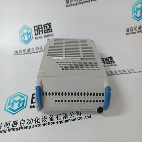
ALSTOM PIB100G 3BEE0226 Control card
- Product ID: PIB100G 3BEE0226
- Brand: ALSTOM
- Place of origin: the United States
- Goods status: new/used
- Delivery date: stock
- The quality assurance period: 365 days
- Phone/WhatsApp/WeChat:+86 15270269218
- Email:stodcdcs@gmail.com
- Tags:ALSTOMPIB100G 3BEE0226Control card
- Get the latest price:Click to consult
The main products
Spare parts spare parts, the DCS control system of PLC system and the robot system spare parts,
Brand advantage: Allen Bradley, BentlyNevada, ABB, Emerson Ovation, Honeywell DCS, Rockwell ICS Triplex, FOXBORO, Schneider PLC, GE Fanuc, Motorola, HIMA, TRICONEX, Prosoft etc. Various kinds of imported industrial parts
Products are widely used in metallurgy, petroleum, glass, aluminum manufacturing, petrochemical industry, coal mine, papermaking, printing, textile printing and dyeing, machinery, electronics, automobile manufacturing, tobacco, plastics machinery, electric power, water conservancy, water treatment/environmental protection, municipal engineering, boiler heating, energy, power transmission and distribution and so on.
ALSTOM PIB100G 3BEE0226 Control card
The optional remote RTD module is designed to be mounted near the motor. This eliminates the need for multiple RTD cables to run back from the motor which may be in a remote location to the switchgear. Although the module is internally shielded to minimize noise pickup and interference, it should be mounted away from high current conductors or sources of strong magnetic fields. The remote RTD module physical dimensions and mounting (drill diagram) are shown below. Mounting hardware (bolts and washers) and instructions are provided with the module.
Correct polarity is also essential. 369 relays must be wired with all ‘+’ terminals connected together, and all ‘–’ terminals connected together. Each relay must be daisy-chained to the next one. Avoid star or stub connected configurations. The last device at each end of the daisy-chain should be terminated with a 120 Ω ¼ watt resistor in series with a 1 nF capacitor across the ‘+’ and ‘–’ terminals. Observing these guidelines will result in a reliable communication system that is immune to system transients.

DISPLAY
All messages are displayed on a 40-character LCD display to make them visible under poor lighting conditions and from various viewing angles. Messages are displayed in plain English and do not require the aid of an instruction manual for deciphering. While the keypad and display are not actively being used, the display will default to user defined status messages. Any trip, alarm, or start inhibit will automatically override the default messages and appear on the display. Contrast Adjustment and Lamp Test: Press the [HELP] key for 2 seconds to initiate lamp test. The contrast can also be adjusted now as required. Use the [VALUE] up and down keys to adjust the contrast. Press the [ENTER] key to save the adjustment when completed.
This port is intended for connection to a portable PC. Setpoint files may be created at any location and downloaded through this port using the 369PC software. Local interrogation of Setpoints and Actual Values is also possible. New firmware may be downloaded to the 369 flash memory through this port. Upgrading of the relay firmware does not require a hardware EPROM change.
The 369 messages are organized
into pages under the main headings, Setpoints and Actual Values. The [SETPOINTS] key is used to navigate through the page headers of the programmable parameters. The [ACTUAL VALUES] key is used to navigate through the page headers of the measured parameters. Each page is broken down further into logical subgroups of messages. The [PAGE] up and down keys may be used to navigate through the subgroups. • [SETPOINTS]: This key may be used to navigate through the page headers of the programmable parameters. Alternately, one can press this key followed by using the Page Up / Page Down keys. • [ACTUAL VALUES]: This key is used to navigate through the page headers of the measured parameters. Alternately, one can scroll through the pages by pressing the Actual Values key followed by using the Page Up / Page Down keys. • [PAGE]: The Page Up/ Page Down keys may be used to scroll through page headers for both Setpoints and Actual Values. • [LINE]: Once the required page is found, the Line Up/ Line Down keys may be used to scroll through the sub-headings. • [VALUE]: The Value Up and Value Down keys are used to scroll through variables in the Setpoint programming mode. It will increment and decrement numerical Setpoint values, or alter yes/no options. • [RESET]: The reset key may be used to reset a trip or latched alarm, provided it has been activated by selecting the local reset. • [ENTER] The key is dual purpose. It is used to enter the subgroups or store altered setpoint values. • [CLEAR] The key is also dual purpose. It may be used to exit the subgroups or to return an altered setpoint to its original value before it has been stored. • [HELP]: The help key may be pressed at any time for context sensitive help messages; such as the Setpoint range, etc.