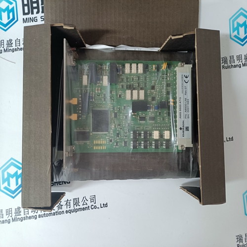
Home > Product > Servo control system > HIMA F8628X controller
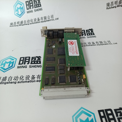
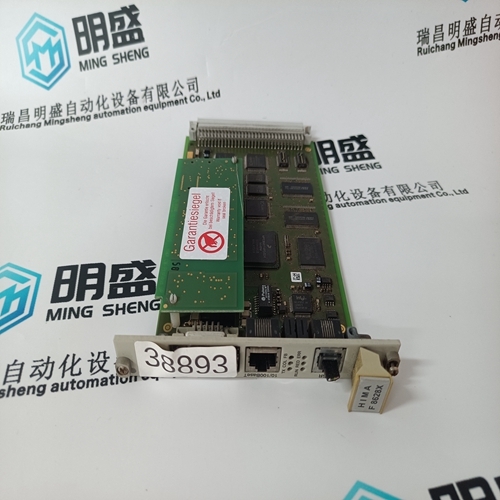
HIMA F8628X controller
- Product ID: F8628X
- Brand: HIMA
- Place of origin: the United States
- Goods status: new/used
- Delivery date: stock
- The quality assurance period: 365 days
- Phone/WhatsApp/WeChat:+86 15270269218
- Email:stodcdcs@gmail.com
- Tags:HIMAF8628Xcontroller
- Get the latest price:Click to consult
The main products
Spare parts spare parts, the DCS control system of PLC system and the robot system spare parts,
Brand advantage: Allen Bradley, BentlyNevada, ABB, Emerson Ovation, Honeywell DCS, Rockwell ICS Triplex, FOXBORO, Schneider PLC, GE Fanuc, Motorola, HIMA, TRICONEX, Prosoft etc. Various kinds of imported industrial parts
Products are widely used in metallurgy, petroleum, glass, aluminum manufacturing, petrochemical industry, coal mine, papermaking, printing, textile printing and dyeing, machinery, electronics, automobile manufacturing, tobacco, plastics machinery, electric power, water conservancy, water treatment/environmental protection, municipal engineering, boiler heating, energy, power transmission and distribution and so on.
HIMA F8628X controller
This section provides some procedures for troubleshooting the 369PC when troubles are encountered within the WindowsTM Environment, e.g. General Protection Fault (GPF), Missing Window, Problems in Opening/Saving Files, and Application Error. If the 369 program causes WindowsTM system errors: • Make sure the PC computer program is installed and meets the minimum requirements. • Make sure only one copy of 369PC is running at a given time: 369PC cannot multi-task.
There are two levels of access security: Read Only and Read & Write. The access terminals (Terminals 57 and 58) must be shorted to gain read/write access via the front panel. The Front Panel Access displays the level of access based on the condition of the access switch. Read Only: Setpoints and Actual Values may be viewed but, not changed. Read & Write: Permits viewing of Actual Values as well as changing and storing of Setpoints Communication access can be changed with the 369PC. The setpoint access menu is located in the Setpoint > S1 Setup menu item. An access tab is shown only when communicating with a relay. To set a password, click on the Change Password button, then enter and verify a new passcode when prompted. After a passcode is entered, Setpoint Access changes to Read Only. When setpoints are changed through 369PC during Read Only access, the passcode must be entered before the new setpoint is stored. To allow extended write access, click Allow Write Access and enter the passcode. To change the access level back to Read Only, click Restrict Write Access. If no setpoints are stored for longer than 30 minutes, or if control power is cycled, access automatically reverts to Read Only.
DISPLAY PREFERENCES
Some of the message characteristics can be modified to suit different situations preferences setpoints. If no keys are pressed for a period of time longer than the default message timeout, the 369 automatically displays a series of default messages. This time can be modified to ensure messages remain on the screen long enough during programming or reading of actual values. Each default message remains on the screen for the default message cycle time. The contrast of the LCD display can be changed for different lighting conditions. If the display is unreadable (dark or light) press the [HELP] key for 2 seconds. This will put the relay in manual contrast adjustment mode. Use the value up or down keys to adjust the contrast level. Press the [ENTER] key when complete. The display update interval controls how often the display is updated. If the displayed readings are fluctuating, the time may be increased to smooth out the readings. Temperatures may be displayed in either Celsius or Fahrenheit degrees. RTD setpoints are programmed in Celsius only
If the access level is Read/Write, write access to setpoints is automatic and a 0 password need not be entered. If the password is not known, consult the factory service department with the ENCRYPTED COMM PASSCODE value to be decoded.
The 369 is equipped with four independent serial ports.
The RS232 port is for local use and responds regardless of the programmed slave address. The rear RS485 communication ports are addressed. If an RRTD module is used in conjunction with the 369, channel 3 must be used for communication between the two devices and the CHANNEL 3 APPLICATION setpoint must be set to "RRTD" (note that the corresponding setting on the RRTD must be set to "MODBUS"). A fiber optic port (Option F) may be ordered for channel 3. If the channel 3 fiber optic port is used, the channel 3 RS485 connection is disabled. The RS232 port may be connected to a personal computer running 369PC. This may be used for downloading and uploading setpoints files, viewing actual values, and upgrading the 369 firmware. See Section 4.2: 369PC INTERFACE on page 4–3 for details on using 369PC. The RS485 ports support a subset of the Modbus RTU protocol. Each port must have a unique address between 1 and 254. Address 0 is the broadcast address listened to by all relays. Addresses need not be sequential; however, no two devices can have the same address. Generally, each addition to the link uses the next higher address, starting at 1. A maximum of 32 devices can be daisy-chained and connected to a DCS, PLC, or PC using the RS485 ports. A repeater may be used to allow more than 32 relays on a single link. The Profibus-DP protocol is supported with the optional Profibus protocol interface (option P). The bus address as Profibus-DP node is set with the PROFIBUS ADDRESS setpoint, with an address range from 1 to 126. Address 126 is used only for commissioning purposes and should not be used to exchange user data. The Modbus/TCP protocol is also supported with the optional Modbus/TCP protocol interface (option E).
