Home > Product > Servo control system > HIMA F8652X controller module
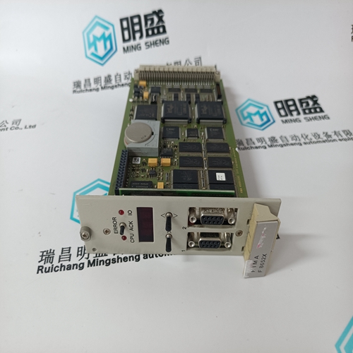
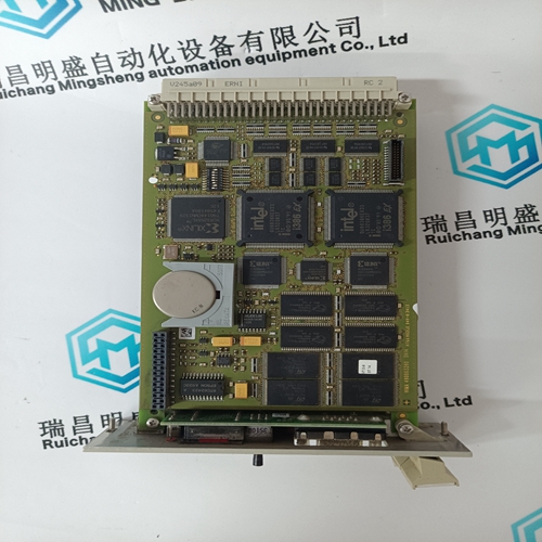
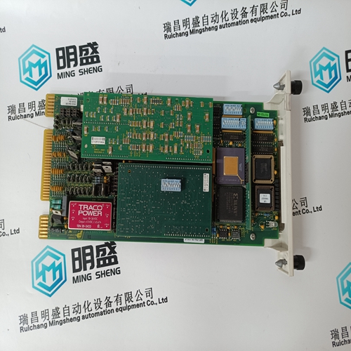
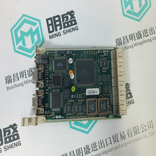
HIMA F8652X controller module
- Product ID: F8652X
- Brand: HIMA
- Place of origin: the United States
- Goods status: new/used
- Delivery date: stock
- The quality assurance period: 365 days
- Phone/WhatsApp/WeChat:+86 15270269218
- Email:stodcdcs@gmail.com
- Tags:HIMAF8652Xcontroller module
- Get the latest price:Click to consult
The main products
Spare parts spare parts, the DCS control system of PLC system and the robot system spare parts,
Brand advantage: Allen Bradley, BentlyNevada, ABB, Emerson Ovation, Honeywell DCS, Rockwell ICS Triplex, FOXBORO, Schneider PLC, GE Fanuc, Motorola, HIMA, TRICONEX, Prosoft etc. Various kinds of imported industrial parts
Products are widely used in metallurgy, petroleum, glass, aluminum manufacturing, petrochemical industry, coal mine, papermaking, printing, textile printing and dyeing, machinery, electronics, automobile manufacturing, tobacco, plastics machinery, electric power, water conservancy, water treatment/environmental protection, municipal engineering, boiler heating, energy, power transmission and distribution and so on.
HIMA F8652X controller module
The time/date stamp is used to track events for diagnostic purposes. The date and time are preset but may be entered manually. A battery backed internal clock runs continuously even when power is off. It has the same accuracy as an electronic watch approximately ±1 minute per month. It may be periodically corrected either manually through the keypad or via the clock update command over the serial link using 369PC. Enter the current date using two digits for the month, two digits for the day, and four digits for the year. For example, July 15, 2001 is entered as "07 15 2001". If entered from the keypad, the new date takes effect the moment the [ENTER] key is pressed. Enter the current time, by using two digits for the hour in 24 hour time, two digits for the minutes, and two digits for the seconds. If entered from the keypad, the new time will take effect the moment the [ENTER] key is pressed. If the serial communication link is used, then all the relays can keep time in synchronization with each other. A new clock time is pre-loaded into the memory map via the communications port by a remote computer to each relay connected on the communications channel. The computer broadcasts (address 0) a “set clock” command to all relays. Then all relays in the system begin timing at the exact same instant. There can be up to 100 ms of delay in receiving serial commands so the clock time in each relay is ±100 ms, ± the absolute clock accuracy, in the PLC or PC (see Chapter 10: COMMUNICATIONS for information on programming the time and synchronizing commands.)

Waveform capture records contain
waveforms captured at the sampling rate as well as contextual information at the point
of trigger. These records are triggered by trip functions, digital input set to capture or via the PC program.
Multiple waveforms are captured simultaneously for each record: Ia, Ib, Ic, Ig, Va, Vb, and Vc.
The trigger position is programmable as a percent of the total buffer size (e.g. 10%, 50%, 75%, etc.). The trigger position
determines the number of pre and post fault cycles the record will be divided into. The relay sampling rate is 16 samples
per cycle.
Five different 40-character message screens can be programmed. These messages may be notes that pertain to the 369 installation. This can be useful for reminding operators to perform certain tasks. The messages are entered through the any of the communications ports. The 369PC software should be used to enter these messages.
PHASE CT PRIMARY
Enter the phase CT primary here. The phase CT secondary (1 A or 5A) is determined by terminal connection to the 369. The phase CT should be chosen such that the motor FLA is between 50% and 100% of the phase CT primary. Ideally the motor FLA should be as close to 100% of phase CT primary as possible, never more. The phase CT class or type should also be chosen such that the CT can handle the maximum potential fault current with the attached burden without having its output saturate. Information on how to determine this if required is available in Section 7.4: CT SPECIFICATION AND SELECTION on page 7–7. MOTOR FLA: The motor FLA (full load amps or full load current) must be entered. This value may be taken from the motor nameplate or motor data sheets.
The 369 displays a series of default messages. These default messages appear after the value for the DEFAULT MESSAGE CYCLE TIME expires and there are no active trips, alarms or start inhibits. See Section 5.2.3: DISPLAY PREFERENCES on page 5–5 for details on setting time delays and message durations. The default messages can be selected from the list above including the five user definable messages from the message scratchpad.