Home > Product > DCS control system > Honeywell SPS5710 51199929-100 Channel interface module
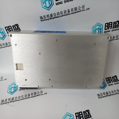
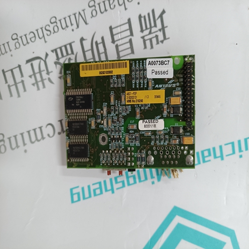
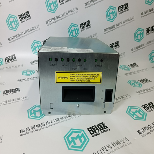
Honeywell SPS5710 51199929-100 Channel interface module
- Product ID: SPS5710 51199929-100
- Brand: HONEYWELL
- Place of origin: The United States
- Goods status: new/used
- Delivery date: stock
- The quality assurance period: 365 days
- Phone/WhatsApp/WeChat:+86 15270269218
- Email:stodcdcs@gmail.com
- Tags:HoneywellSPS5710 51199929-100Channel interface module
- Get the latest price:Click to consult
The main products
Spare parts spare parts, the DCS control system of PLC system and the robot system spare parts,
Brand advantage: Allen Bradley, BentlyNevada, ABB, Emerson Ovation, Honeywell DCS, Rockwell ICS Triplex, FOXBORO, Schneider PLC, GE Fanuc, Motorola, HIMA, TRICONEX, Prosoft etc. Various kinds of imported industrial parts
Products are widely used in metallurgy, petroleum, glass, aluminum manufacturing, petrochemical industry, coal mine, papermaking, printing, textile printing and dyeing, machinery, electronics, automobile manufacturing, tobacco, plastics machinery, electric power, water conservancy, water treatment/environmental protection, municipal engineering, boiler heating, energy, power transmission and distribution and so on.
Honeywell SPS5710 51199929-100 Channel interface module
GROUND CT TYPE / GROUND CT PRIMARY: The GROUND CT TYPE and GROUND CT PRIMARY (if 5 A or 1 A secondary) must be entered here. For high resistance grounded systems, sensitive ground detection is possible with the 50:0.025 CT. On solidly or low resistance grounded systems where fault current can be quite high, a 1 A or 5 A CT should be used for either zero-sequence (core balance) or residual ground sensing. If a residual connection is used with the phase CTs, the phase CT primary must also be entered for the ground CT primary. As with the phase CTs the type of ground CT should be chosen to handle all potential fault levels without saturating. VT CONNECTION TYPE / VT RATIO / MOTOR RATED VOLTAGE: These voltage related setpoints are visible only if the 369 has metering installed. The manner in which the voltage transformers are connected must be entered here or none if VTs are not used. The VT turns ratio must be chosen such that the secondary voltage of the VTs is between 40 and 240 V when the primary is at motor nameplate voltage. All voltage protection features are programmed as a percent of motor nameplate or rated voltage which represents the rated motor design voltage line to line. For example: If the motor nameplate voltage is 4160 V and the VTs are 4160/120 open-delta, program the following: VT CONNECTION TYPE: Open Delta VT RATIO: 34.67:1 MOTOR RATED VOLTAGE: 4160 V
NOMINAL FREQUENCY
Enter the nominal system frequency here. This setpoint allows the 369 to determine the internal sampling rate for maximum accuracy. Frequency is normally determined from the Va voltage input. If however this voltage drops below the minimum voltage threshold the Ia current input will be used. SYSTEM PHASE SEQUENCE: If the phase sequence for a given system is ACB rather than the standard ABC the phase sequence may be changed. This setpoint allows the 369 to properly calculate phase reversal and power quantities and is only visible if the 369 has metering installed.
When the Trip Counter is enabled and the alarm pickup level is reached, an alarm will occur. To reset the alarm the trip counter must be cleared (see Section 5.2.9: CLEAR/PRESET DATA on page 5–10 for details) or the pickup level increased and the reset key pressed (if a latched alarm). The trip counter alarm can be used to monitor and alarm when a predefined number of trips occur. This would then prompt the operator or supervisor to investigate the causes of the trips that have occurred. Details of individual trip counters can be found in the Motor Statistics section of Actual Values page 4 (see Section 6.5.3: MOTOR STATISTICS on page 6–17).
SYSTEM SETUP
If the Starter Failure alarm feature is enabled, any time the 369 initiates a trip, the 369 will monitor the Starter Status input (if assigned to "Spare Switch" in S9 DIGITAL INPUTS) and the motor current. If the starter status contacts do not change state or motor current does not drop to zero after the programmed time delay, an alarm will occur. The time delay should be slightly longer than the breaker or contactor operating time. In the event that an alarm does occur, if Breaker was chosen as the starter type, the alarm will be Breaker Failure. If on the other hand, Contactor was chosen for starter type, the alarm will be Welded Contactor.
The 369 can measure the demand of the motor for several parameters (current, kW, kvar, kVA). The demand values may be of interest for energy management programs where processes may be altered or scheduled to reduce overall demand on a feeder. An alarm will occur if the limit of any of the enabled demand elements is reached. Demand is calculated in the following manner. Every minute, an average magnitude is calculated for current, +kW, +kvar, and kVA based on samples taken every 5 seconds. These values are stored in a FIFO (First In, First Out buffer). The size of the buffer is determined by the period selected for the setpoint. The average value of the buffer contents is calculated and stored as the new demand value every minute. Demand for real and reactive power is only positive quantities (+kW and +kvar).