Home > Product > DCS control system > PP865A 3BSE042236R2 Touch screen
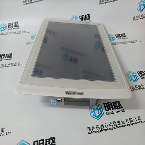
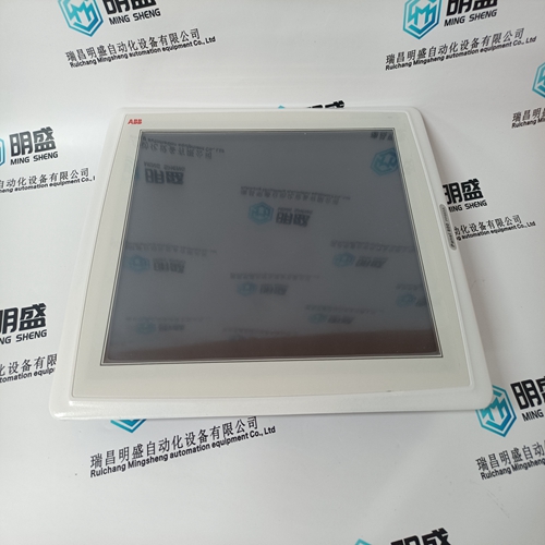
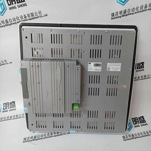
PP865A 3BSE042236R2 Touch screen
- Product ID: PP865A 3BSE042236R2
- Brand: ABB
- Place of origin: The Swiss
- Goods status: new/used
- Delivery date: stock
- The quality assurance period: 365 days
- Phone/WhatsApp/WeChat:+86 15270269218
- Email:stodcdcs@gmail.com
- Tags:PP865A 3BSE042236R2Touch screen
- Get the latest price:Click to consult
The main products
Spare parts spare parts, the DCS control system of PLC system and the robot system spare parts,
Brand advantage: Allen Bradley, BentlyNevada, ABB, Emerson Ovation, Honeywell DCS, Rockwell ICS Triplex, FOXBORO, Schneider PLC, GE Fanuc, Motorola, HIMA, TRICONEX, Prosoft etc. Various kinds of imported industrial parts
Products are widely used in metallurgy, petroleum, glass, aluminum manufacturing, petrochemical industry, coal mine, papermaking, printing, textile printing and dyeing, machinery, electronics, automobile manufacturing, tobacco, plastics machinery, electric power, water conservancy, water treatment/environmental protection, municipal engineering, boiler heating, energy, power transmission and distribution and so on.
PP865A 3BSE042236R2 Touch screen
If this feature is used, Starter Status Switch input must be either from a common control contact or a parallel combination of Auxiliary ‘a’ contacts or a series combination of Auxiliary ‘b’ contacts from the reduced voltage contactor and the full voltage contactor. Once transition is initiated, the 369 will assume the motor is still running for at least 2 seconds. This will prevent the 369 from recognizing an additional start if motor current goes to zero during an open transition.
Heat is one of the principle enemies of motor life. When a motor is specified, the purchaser communicates to the manufacturer what the loading conditions, duty cycle, environment and pertinent information about the driven load such as starting torque. The manufacturer then provides a stock motor or builds a motor that should have a reasonable life under those conditions. The purchaser should request all safe stall, acceleration and running thermal limits for all motors they receive in order to effectively program the 369.
The 369 can be configured
to automatically restart a motor in the event of a trip. When enabled, a restart timer will be loaded with the programmed timer values and trigger a designated output contact to operate when the timer expires. This contact can be wired with OR logic in the start circuit of the motor. This feature is very useful in remote pumping applications where the pumping station may be unmanned and an autoreclosure of contacts or breakers is required. The autorestart implementation requires specific criteria to be present to allow motor restarting. The 369 will not attempt to restart after any Short Circuit or Ground Fault trip, and only one autorestart is attempted after an Overload trip, provided the Single Shot Restart feature is enabled. In this mode, the 369 start inhibit will be active for the lockout time upon the second consecutive Overload trip. The 369 also requires that TRIP RELAY RESET MODE be set to "Remote Only" or "All Resets". Upon determination of a successful restart attempt, the SERIAL COMMUNICATION CONTROL must be enabled and an output contact assigned in the ASSIGNED START CONTROL RELAYS setpoint (these settings are found in S2 SYSTEM SETUP \ CONTROL FUNCTIONS). The 369 uses the logic shown in Figure 5–5: AUTORESTART LOGIC on the following page to determine restart conditions.
The base delay time is set with the RESTART DELAY setpoint.
The PROGRESSIVE DELAY setpoint is used to progressively add time to the total restart delay based upon the number of restarts. The HOLD DELAY is used to sequentially stagger restarts of a series of motors on a bus in the event of the entire bus being brought online. For example, four motors on a bus may have settings of 60, 120, 180, and 240 seconds, respectively. In the event of a common fault, the motors are brought online in sequence. The minimizes the effect of voltage sag on the bus when each motor is brought online. The last criteria for a valid restart attempt is determined by the BUS VALID ENABLED/LEVELS setpoints. When enabled, the 369 determines the average line voltage at the motor prior to restart and blocks an attempt if the voltage is below the BUS VALID LEVEL setpoint. The setpoint is in terms of the S2 SYSTEM SETUP \ CT/VT SETUP \ MOTOR RATED VOLTAGE setpoint. The 369 only examines this threshold at the instant of issuing a restart command to the designated output contact. This gives time for the bus to settle after the trip has occurred. This setpoint is only available if the Metering Option (M) is enabled.