Home > Product > Servo control system > VT-HNC100-1-23/W-08-0-0 R900955334 Driver module
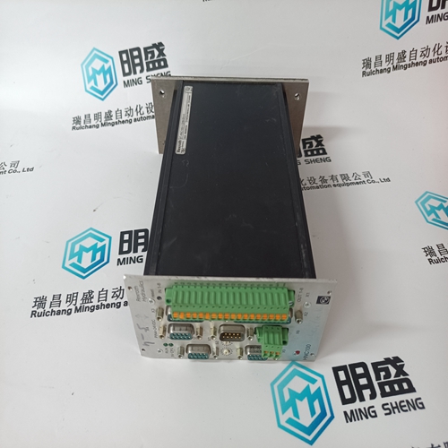
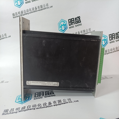
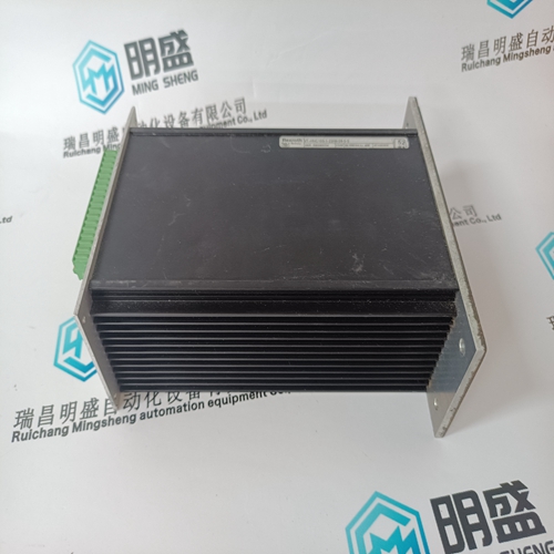
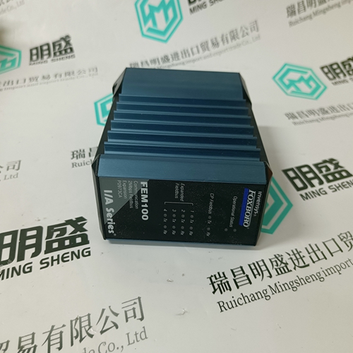
VT-HNC100-1-23/W-08-0-0 R900955334 Driver module
- Product ID: VT-HNC100-1-23/W-08-0-0 R900955334
- Brand: Rexroth
- Place of origin: the United States
- Goods status: new/used
- Delivery date: stock
- The quality assurance period: 365 days
- Phone/WhatsApp/WeChat:+86 15270269218
- Email:stodcdcs@gmail.com
- Tags:VT-HNC100-1-23/W-08-0-0R900955334Driver module
- Get the latest price:Click to consult
The main products
Spare parts spare parts, the DCS control system of PLC system and the robot system spare parts,
Brand advantage: Allen Bradley, BentlyNevada, ABB, Emerson Ovation, Honeywell DCS, Rockwell ICS Triplex, FOXBORO, Schneider PLC, GE Fanuc, Motorola, HIMA, TRICONEX, Prosoft etc. Various kinds of imported industrial parts
Products are widely used in metallurgy, petroleum, glass, aluminum manufacturing, petrochemical industry, coal mine, papermaking, printing, textile printing and dyeing, machinery, electronics, automobile manufacturing, tobacco, plastics machinery, electric power, water conservancy, water treatment/environmental protection, municipal engineering, boiler heating, energy, power transmission and distribution and so on.
VT-HNC100-1-23/W-08-0-0 R900955334 Driver module
Motor thermal limits are dictated by the design of the stator and the rotor. Motors have three modes of operation: locked rotor or stall (rotor is not turning), acceleration (rotor is coming up to speed), and running (rotor turns at near synchronous speed). Heating occurs in the motor during each of these conditions in very distinct ways. Typically, during motor starting, locked rotor, and acceleration conditions, the motor is rotor limited. That is, the rotor approaches its thermal limit before the stator. Under locked rotor conditions, voltage is induced in the rotor at line frequency, 50 or 60 Hz. This voltage causes a current to flow in the rotor, also at line frequency, and the heat generated (I 2R) is a function of the effective rotor resistance. At 50 / Hz, the rotor cage reactance causes the current to flow at the outer edges of the rotor bars. The effective resistance of the rotor is therefore at a maximum during a locked rotor condition as is rotor heating. When the motor is running at rated speed, the voltage induced in the rotor is at a low frequency (approximately 1 Hz) and therefore, the effective resistance of the rotor is reduced quite dramatically.
During running overloads
the motor thermal limit is typically dictated by stator parameters. Some special motors might be all stator or all rotor limited. During acceleration, the dynamic nature of the motor slip dictates that rotor impedance is also dynamic, and a third overload thermal limit characteristic is necessary. Typical thermal limit curves are shown below. The motor starting characteristic is shown for a high inertia load at 80% voltage. If the motor started quicker, the distinct characteristics of the thermal limit curves would not be required and the running overload curve would be joined with locked rotor safe stall times to produce a single overload curve.
The primary protective function
of the 369 is the thermal model. It consists of five key elements: the overload curve and pickup level, unbalance biasing, motor cooling time constants, and temperature biasing based on Hot/Cold motor information and measured stator RTD temperature. The 369 integrates both stator and rotor heating into one model. Motor heating is reflected in the THERMAL CAPACITY USED actual value. If stopped for a long period of time, the motor will be at ambient temperature and THERMAL CAPACITY USED should be zero. If the motor is in overload, a trip will occur once the thermal capacity used reaches 100%. Insulation does not immediately melt when a motor’s thermal limit is exceeded. Rather, the rate of insulation degradation reaches a point where the motor life will be significantly reduced if the condition persists. The thermal capacity used alarm may be used as a warning of an impending overload trip.
STANDARD OVERLOAD CURVE
The overload curve accounts for motor heating during stall, acceleration, and running in both the stator and the rotor. The OVERLOAD PICKUP setpoint dictates where the running overload curve begins as the motor enters an overload condition. This is useful for service factor motors as it allows the pickup level to be defined. The curve is effectively cut off at current values below this pickup. Motor thermal limits consist of three distinct parts based on the three conditions of operation, locked rotor or stall, acceleration, and running overload. Each of these curves may be provided for both a hot motor and a cold motor. A hot motor is defined as one that has been running for a period of time at full load such that the stator and rotor temperatures have settled at their rated temperature. A cold motor is defined as a motor that has been stopped for a period of time such that the stator and rotor temperatures have settled at ambient temperature. For most motors, the distinct characteristics of the motor thermal limits are formed into one smooth homogeneous curve. Sometimes only a safe stall time is provided. This is acceptable if the motor has been designed conservatively and can easily perform its required duty without infringing on the thermal limit. In this case, the protection can be conservative and process integrity is not compromised. If a motor has been designed very close to its thermal limits when operated as required, then the distinct characteristics of the thermal limits become important.