Home > Product > Robot control system > SCHROFF MPS022 13100203 Power supply
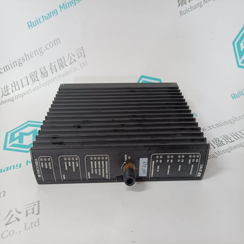
SCHROFF MPS022 13100203 Power supply
- Product ID: MPS022 13100203
- Brand: SCHROFF
- Place of origin: the United States
- Goods status: new/used
- Delivery date: stock
- The quality assurance period: 365 days
- Phone/WhatsApp/WeChat:+86 15270269218
- Email:stodcdcs@gmail.com
- Tags:SCHROFFMPS022 13100203Power supply
- Get the latest price:Click to consult
The main products
Spare parts spare parts, the DCS control system of PLC system and the robot system spare parts,
Brand advantage: Allen Bradley, BentlyNevada, ABB, Emerson Ovation, Honeywell DCS, Rockwell ICS Triplex, FOXBORO, Schneider PLC, GE Fanuc, Motorola, HIMA, TRICONEX, Prosoft etc. Various kinds of imported industrial parts
Products are widely used in metallurgy, petroleum, glass, aluminum manufacturing, petrochemical industry, coal mine, papermaking, printing, textile printing and dyeing, machinery, electronics, automobile manufacturing, tobacco, plastics machinery, electric power, water conservancy, water treatment/environmental protection, municipal engineering, boiler heating, energy, power transmission and distribution and so on.
SCHROFF MPS022 13100203 Power supply
If the motor starting current begins to infringe on the thermal damage curves, it may be necessary to use a custom curve to ensure successful starting without compromising motor protection. Furthermore, the characteristics of the starting thermal damage curve (locked rotor and acceleration) and the running thermal damage curves may not fit together very smoothly. In this instance, it may be necessary to use a custom curve to tailor protection to the motor thermal limits so the motor may be started successfully and used to its full potential without compromising protection. The distinct parts of the thermal limit curves now become more critical. For these conditions, it is recommended that the 369 custom curve thermal model be used. The custom overload curve of the 369 allows the user to program their own curve by entering trip times for 30 predetermined current levels. The 369 smooths the areas between these points to make the protection curve. It can be seen below that if the running overload thermal limit curve were smoothed into one curve with the locked rotor overload curve, the motor could not start at 80% line voltage. A custom curve is required.

UNBALANCE BIAS
Unbalanced phase currents cause additional rotor heating not accounted for by electromechanical relays and may not be accounted for in some electronic protective relays. When the motor is running, the rotor rotates in the direction of the positive-sequence current at near synchronous speed. Negative-sequence current, having a phase rotation opposite to the positive sequence current, and hence, opposite to the rotor rotation, generates a rotor voltage that produces a substantial rotor current. This induced current has a frequency approximately twice the line frequency: 100 Hz for a 50 Hz system, 120 Hz for a 60 Hz system. Skin effect in the rotor bars at this frequency causes a significant increase in rotor resistance, and therefore a significant increase in rotor heating. This extra heating is not accounted for in the motor manufacturer thermal limit curves, since these curves assume positive-sequence currents only from a perfectly balanced supply and motor design.
The thermal capacity used quantity
is reduced in an exponential manner when the motor is stopped or current is below the overload pickup setpoint. This reduction simulates motor cooling. The motor cooling time constants should be entered for both the stopped and running cases. A stopped motor will normally cool significantly slower than a running motor. Note that the cool time constant is one fifth the total cool time from 100% thermal capacity used down to 0% thermal capacity used. The 369 can learn and estimate the stopped and running cool time constants for a motor. Calculation of a cool time constant is performed whenever the motor state transitions from starting to running or from running to stopped. The learned cool times are based on the cooling rate of the hottest stator RTD, the hot/cold ratio, the ambient temperature (40 if no ambient RTD), the measured motor load and the programmed service factor or overload pickup. Learned values should only be enabled for motors that have been started, stopped and run at least five times.
The figure on the left shows motor derating as a function of voltage unbalance as recommended by the American organization NEMA (National Electrical Manufacturers Association). Assuming a typical induction motor with an inrush of 6 × FLA and a negative sequence impedance of 0.167, voltage unbalances of 1, 2, 3, 4, and 5% equal current unbalances of 6, 12, 18, 24, and 30% respectively. Based on this assumption, the figure on the right below illustrates the amount of motor derating for different values of k entered for the setpoint UNBALANCE BIAS K FACTOR. Note that the curve for k = 8 is almost identical to the NEMA derating curve.