Home > Product > DCS control system > ICSE08B5 Remote input module
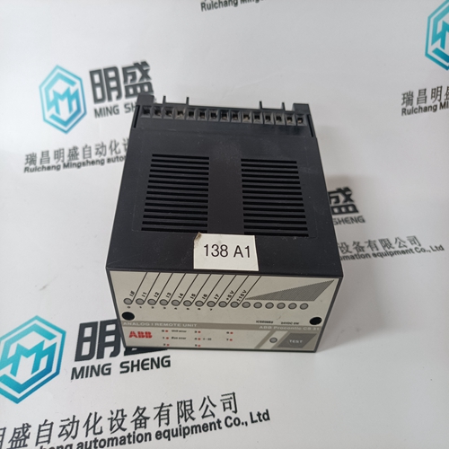
ICSE08B5 Remote input module
- Product ID: ICSE08B5
- Brand: ABB
- Place of origin: The Swiss
- Goods status: new/used
- Delivery date: stock
- The quality assurance period: 365 days
- Phone/WhatsApp/WeChat:+86 15270269218
- Email:stodcdcs@gmail.com
- Tags:ICSE08B5Remote input module
- Get the latest price:Click to consult
The main products
Spare parts spare parts, the DCS control system of PLC system and the robot system spare parts,
Brand advantage: Allen Bradley, BentlyNevada, ABB, Emerson Ovation, Honeywell DCS, Rockwell ICS Triplex, FOXBORO, Schneider PLC, GE Fanuc, Motorola, HIMA, TRICONEX, Prosoft etc. Various kinds of imported industrial parts
Products are widely used in metallurgy, petroleum, glass, aluminum manufacturing, petrochemical industry, coal mine, papermaking, printing, textile printing and dyeing, machinery, electronics, automobile manufacturing, tobacco, plastics machinery, electric power, water conservancy, water treatment/environmental protection, municipal engineering, boiler heating, energy, power transmission and distribution and so on.
ICSE08B5 Remote input module
RESTART BLOCK: Restart Block may be used to ensure that a certain amount of time passes between stopping a motor and restarting that motor. This timer feature may be very useful for some process applications or motor considerations. If a motor is on a down-hole pump, after the motor stops, the liquid may fall back down the pipe and spin the rotor backwards. It would be very undesirable to start the motor at this time. In another scenario, a motor may be driving a very high inertia load. Once the supply to the motor is disconnected, the rotor may continue to turn for a long period of time as it decelerates. The motor has now become a generator and applying supply voltage out of phase may result in catastrophic failure. ASSIGN INHIBIT RELAY: The relay(s) assigned here will be used for all blocking/inhibit elements in this section. The assigned relay will activate only when the motor is stopped. When a block/inhibit condition times out or is cleared, the assigned relay will automatically reset itself.
NOTES FOR ALL INHIBITS AND BLOCKS: 1. In the event of control power loss, all lockout times will be saved. Elapsed time will be recorded and decremented from the inhibit times whether control power is applied or not. Upon control power being re-established to the 369, all remaining inhibits (have not time out) will be re-activated. 2. If the motor is started while an inhibit is active an event titled ‘Start while Blocked’ will be recorded.

Immediately after the motor is stopped
backspin detection commences and a backspin start inhibit is activated to prevent the motor from being restarted. The backspin frequency is sensed through the BSD voltage input. If the measured frequency is below the programmed Minimum Permissible Frequency, the backspin start inhibit will be removed. The time for the motor to reach the Minimum Permissible Frequency is calculated throughout the backspin state. If the BSD frequency signal is lost prior to reaching the Minimum Permissible Frequency, the inhibit remains active until the predication time has expired. The calculated Predication Time and the Backspin State can be viewed in Voltage metering section of Actual Values page 2. APPLICATION: Backspin protection is typically used on down hole pump motors which can be located several kilometers underground. Check valves are often used to prevent flow reversal when the pump stops. Very often however, the flow reverses due to faulty or non existent check valves, causing the pump impeller to rotate the motor in the reverse direction. Starting the motor during this period of reverse rotation (back-spinning) may result in motor damage. Backspin detection ensures that the motor can only be started when the motor has slowed to within acceptable limits. Without backspin detection a long time delay had to be used as a start permissive to ensure the motor had slowed to a safe speed.
APPLICATION
Each individual RTD may be assigned an application. A setting of "None" turns an individual RTD off. Only RTDs with the application set to "Stator" are used for RTD biasing of the thermal model. If an RTD application is set to "Ambient", then its is used in calculating the learned cool time of the motor. TYPE: Each RTD is individually assigned the RTD type it is connected to. Multiple types may be used with a single 369. NAME: Each RTD may have 8 character name assigned to it. This name is used in alarm and trip messages. ALARM / HI ALARM / TRIP: Each RTD can be programmed for separate Alarm, Hi Alarm and Trip levels and relays. Trips are automatically stored as events. Alarms and Hi Alarms are stored as events only if the Record Alarms as Events setpoint for that RTD is set to Yes. TRIP VOTING: This feature provides added RTD trip reliability in situations where malfunction and nuisance tripping is common. If enabled, the RTD trips only if the RTD (or RTDs) to be voted with are also above their trip level. For example, if RTD 1 is set to vote with All Stator RTDs, the 369 will only trip if RTD 1 is above its trip level and any one of the other stator RTDs is also above its own trip level. RTD voting is typically only used on Stator RTDs and typically done between adjacent RTDs to detect hot spots. Stator RTDs can detect heating due to non overload (current) conditions such as blocked or inadequate cooling and ventilation or high ambient temperature as well as heating due to overload conditions. Bearing or other RTDs can detect overheating of bearings or auxiliary equipment.