Home > Product > DCS control system > YOKOGAWA CP451-51 Processing module
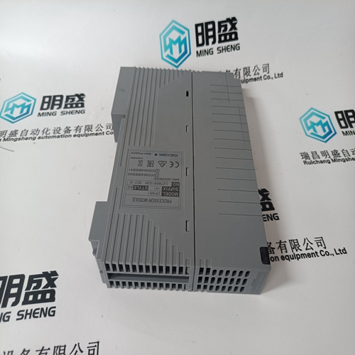
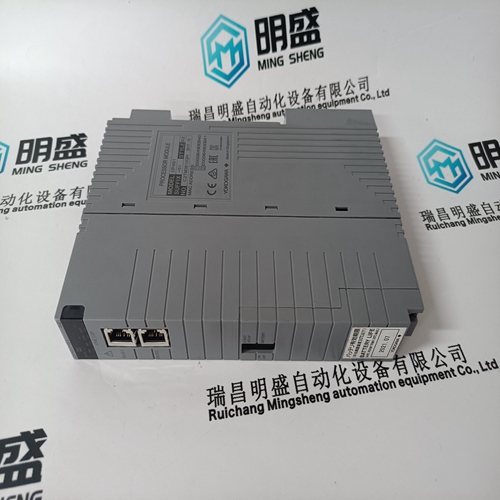
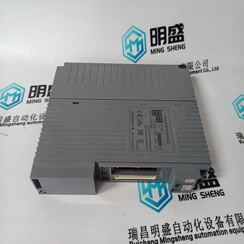
YOKOGAWA CP451-51 Processing module
- Product ID: CP451-51
- Brand: YOKOGAWA
- Place of origin: Japan
- Goods status: new/used
- Delivery date: stock
- The quality assurance period: 365 days
- Phone/WhatsApp/WeChat:+86 15270269218
- Email:stodcdcs@gmail.com
- Tags:YOKOGAWACP451-51Processing module
- Get the latest price:Click to consult
The main products
Spare parts spare parts, the DCS control system of PLC system and the robot system spare parts,
Brand advantage: Allen Bradley, BentlyNevada, ABB, Emerson Ovation, Honeywell DCS, Rockwell ICS Triplex, FOXBORO, Schneider PLC, GE Fanuc, Motorola, HIMA, TRICONEX, Prosoft etc. Various kinds of imported industrial parts
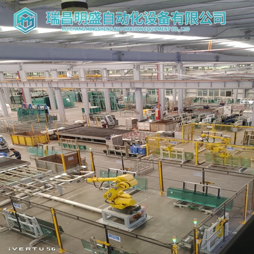
Products are widely used in metallurgy, petroleum, glass, aluminum manufacturing, petrochemical industry, coal mine, papermaking, printing, textile printing and dyeing, machinery, electronics, automobile manufacturing, tobacco, plastics machinery, electric power, water conservancy, water treatment/environmental protection, municipal engineering, boiler heating, energy, power transmission and distribution and so on.
YOKOGAWA CP451-51 Processing module
A breakdown of the last 65535 events is available here along with the cause of the event and the date and time. All trips automatically trigger an event. Alarms only trigger an event if turned on for that alarm. Loss or application of control power, service alarm and emergency restart opening and closing also triggers an event. After 65535 events have been recorded, the oldest one is removed when a new one is added. The event record may be cleared in the setpoints page 1, clear/preset data, clear event record section.The above results indicate a worst-case scenario at the lowest end of the frequency spectrum. Lower frequencies are typically experienced during initial motor starting. The starting settings can be adjusted to compensate for these differences during the short duration of the motor start. During normal motor operating conditions above 25 Hz, the 369 frequency response is such that compensation is not required for current-based protection elements. 7. Cannot store setpoint into the relay. Check and ensure the ACCESS switch is shorted, and check for any PASSCODE restrictions.
Always check the power supply rating
before applying power to the relay Applying voltage greater than the maximum rating to the power supply (e.g. 120 V AC to the low-voltage rated power supply) could result in component damage to the relay's power supply. This will result in the unit no longer being able to power up. Ensure that the 369 nominal phase current of 1 A or 5 A matches the secondary rating and the connections of the connected CTs Unmatched CTs may result in equipment damage or inadequate protection. Ensure that the source CT and VT polarity match the relay CT and VT polarity Polarity of the Phase CTs is critical for power measurement, and residual ground current detection (if used). Polarity of the VTs is critical for correct power measurement and voltage phase reversal operation. Properly ground the 369 Connect both the Filter Ground (terminal 123) and Safety Ground (terminal 126) of the 369 directly to the main GROUND BUS. The benefits of proper grounding of the 369 are numerous, e.g, • Elimination of nuisance tripping • Elimination of internal hardware failures • Reliable operation of the relay • Higher MTBF (Mean Time Between Failures) • It is recommended that a tinned copper braided shielding and bonding cable be used. A Belden 8660 cable or equivalent should be used as a minimum to connect the relay directly to the ground bus.
Grounding of Phase and Ground CTs
All Phase and Ground CTs must be grounded. The potential difference between the CT's ground and the ground bus should be minimal (ideally zero). It is highly recommended that the two CT leads be twisted together to minimize noise pickup, especially when the highly sensitive 50:0.025 Ground CT sensor is used. RTDs Consult the application notes of the 369 Instruction Manual for the full description of the 369 RTD circuitry and the different RTD wiring schemes acceptable for proper operation. However, for best results the following recommendations should be adhered to: a) Use a 3 wire twisted, shielded cable to connect the RTDs from the motor to the 369. The shields should be connected to the proper terminals on the back of the 369. b) RTD shields are internally connected to the 369 ground (terminal #126) and must not be grounded anywhere else. c) RTD signals can be characterized as very small, sensitive signals. Therefore, cables carrying RTD signals should be routed as far away as possible from power carrying cables such as power supply and CT cables. d) If after wiring the RTD leads to the 369, the RTD temperature displayed by the Relay is zero, then check for the following conditions: 1. Shorted RTD 2. RTD hot and compensation leads are reversed, i.e. hot lead in compensation terminal and compensation lead in hot terminal.