Home > Product > DCS control system > 3ASC25H208 DATX100 Digital input card


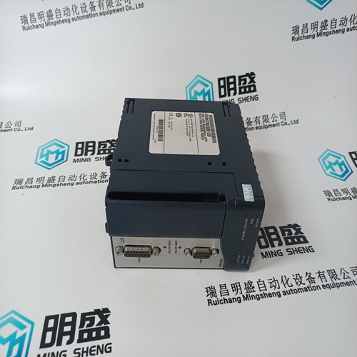
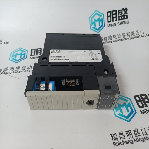
3ASC25H208 DATX100 Digital input card
- Product ID: 3ASC25H208 DATX100
- Brand: ABB
- Place of origin: The Swiss
- Goods status: new/used
- Delivery date: stock
- The quality assurance period: 365 days
- Phone/WhatsApp/WeChat:+86 15270269218
- Email:stodcdcs@gmail.com
- Tags:3ASC25H208 DATX100Digital input card
- Get the latest price:Click to consult
The main products
Spare parts spare parts, the DCS control system of PLC system and the robot system spare parts,
Brand advantage: Allen Bradley, BentlyNevada, ABB, Emerson Ovation, Honeywell DCS, Rockwell ICS Triplex, FOXBORO, Schneider PLC, GE Fanuc, Motorola, HIMA, TRICONEX, Prosoft etc. Various kinds of imported industrial parts
Products are widely used in metallurgy, petroleum, glass, aluminum manufacturing, petrochemical industry, coal mine, papermaking, printing, textile printing and dyeing, machinery, electronics, automobile manufacturing, tobacco, plastics machinery, electric power, water conservancy, water treatment/environmental protection, municipal engineering, boiler heating, energy, power transmission and distribution and so on.
3ASC25H208 DATX100 Digital input card
Set-up Area and Required Environmental Conditions Please note the following information regarding the set-up area: Allow sufficient space for access to the. The connections must be easily accessible. Access to the Central Unit in the LV compartment must be easy for the following reasons: to replace the unit, to expand the unit, to replace specific electronic equipment boards and to replace specific modules if necessary. Because the unit is sensitive to non-permitted severe environmental conditions, please observe the following: The set-up area must be free of excessive air contamination (dust, aggressive substances…). The natural air circulation around the unit must be free. The set-up area must maintain the specified environmental conditions
To connect to the upper level automation system with MODBUS RTU a twisted pair cable shall be used. If the cable is shielded, connect only one side of the shield to the earth screw of the housing. The maximum baud rate is 115000 bit/s. The cable length should not exceed 130 m

Checking the current transformer circuits
To check that the current transformer and the current transformer circuits are wired correctly, run the following checks: Polarity check The polarity check (as close as possible to the REF542plus) is used to check the current circuit and also the installation position and the polarity of the transducer. The polarity of the transducers to one another can also be checked with load current. Current feed with heavy current source (primary test instrument). The current feed provides information on the transducer transformation and the correct wiring to the REF542plus. The power supply should be per conductor and run from conductor to conductor in each case. All line currents and the residual current should be checked here. The transducer transformation can also be checked with load current. Recording the magnetizing characteristic Recording the magnetizing characteristic ensures that the REF542plus is connected to a protective core and not to a measuring core. Checking the transducer circuit ground Every independent current circuit may be grounded at only one point to prevent balancing currents resulting from potential differences. Check the grounding of the cable current transformer (when used) If the neutral current is measured by a cable current transformer, the cable shielding should first be returned through the cable current transformer before connecting it to the ground.
Wiring the REF542plus
Follow the bay documentation supplied for the wiring. In conclusion, the checks described in the following paragraphs can be done to ensure that the wiring is correctly installed.This enables weak ground faults currents that flow along the cable sheath to dissipate. In this way, they will not be incorrectly measured at their own relay feeder. The following shows another view of the cable current transformer grounding.
Check the voltage transformer circuits To check that the voltage transformer and the voltage transformer circuits are wired correctly, run the following checks: Polarity check Wiring check Check the transformer circuit grounding Check the voltage transformer for neutral point-ground voltage (when used). To measure ground faults please proceed as follows: The voltage is referred to as neutral point-ground voltage of a ground fault measurement when it occurs with a metallic ground fault in the network between terminals "e“ and "n“ of the open delta winding. In the event of a metallic ground fault in phase L1, the external phase-to-neutral voltages occur in phases L2 and L3 instead of the conductor-ground voltages. They are added geometrically and yield three times the amplitude between terminals "e“ and "n“.