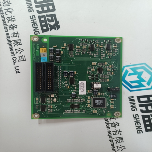
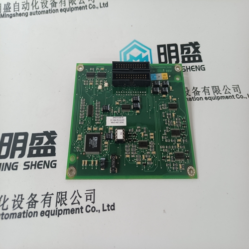
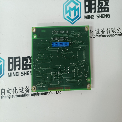
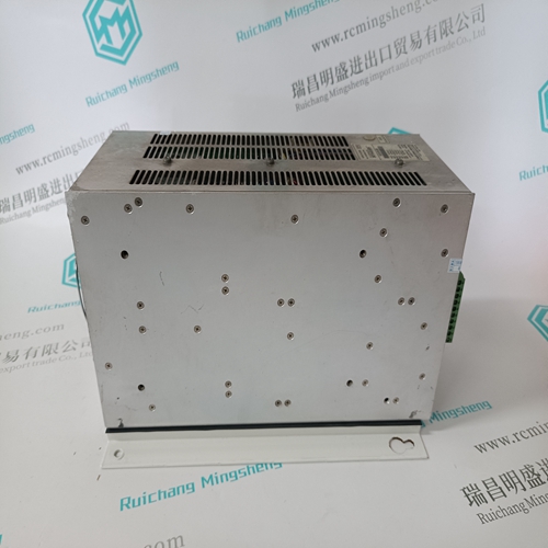
Home > Product > DCS control system > 3ASC25H216A DATX132 Digital output card
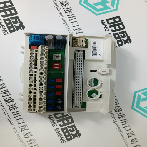
3ASC25H216A DATX132 Digital output card
- Product ID: 3ASC25H216A DATX132
- Brand: ABB
- Place of origin: The Swiss
- Goods status: new/used
- Delivery date: stock
- The quality assurance period: 365 days
- Phone/WhatsApp/WeChat:+86 15270269218
- Email:stodcdcs@gmail.com
- Tags:3ASC25H216A DATX132Digital output card
- Get the latest price:Click to consult
The main products
Spare parts spare parts, the DCS control system of PLC system and the robot system spare parts,
Brand advantage: Allen Bradley, BentlyNevada, ABB, Emerson Ovation, Honeywell DCS, Rockwell ICS Triplex, FOXBORO, Schneider PLC, GE Fanuc, Motorola, HIMA, TRICONEX, Prosoft etc. Various kinds of imported industrial parts
Products are widely used in metallurgy, petroleum, glass, aluminum manufacturing, petrochemical industry, coal mine, papermaking, printing, textile printing and dyeing, machinery, electronics, automobile manufacturing, tobacco, plastics machinery, electric power, water conservancy, water treatment/environmental protection, municipal engineering, boiler heating, energy, power transmission and distribution and so on.
3ASC25H216A DATX132 Digital output card
This polarity check, also referred to as patch test, must be run for every core. To guarantee correct operation even with a multi core current transformer with different cores such as protection and measuring cores, it is recommended that the magnetizing characteristic (hysteresis) be recorded. A Variac with appropriately high voltage is connected to the secondary terminals. The flowing current is measured while the output voltage is rising. The characteristic of the measured values, voltage over current, yields the magnetizing characteristic of the core, which can then be compared with the manufacturer's data. The transformation ratio of the current transformer cores is checked with a special primary current feed device. The feed device is primarily connected to the current transformer and the secondary value is measured at the secondary terminals of the transformer or at the protective cabinet with an ampere meter.
The same polarity test or patch test is run with voltage transformers. The difference is that the battery is connected to the secondary side and the analog DC test instrument to the primary coil of the voltage transformer. The test setup for checking a core is shown in the following figure.
Every core must be tested here
If the Variac described in the current transformer section for recording the magnetizing characteristic has a sufficiently high output voltage (e.g. 500 V), it can also be used to run a qualitative test of the voltage transformer transformation ratio. The Variac voltage is applied to the primary side of the voltage transformer and a voltmeter is used to measure the secondary voltage at the corresponding transformer or protective cabinet terminals. 5.5.3 Current sensor Because the current sensor, the Rogowski coil, is an air-core coil, it must be subjected to the same polarity test as the current transformers. The test design is shown in the following diagram. A higher voltage value may be required for the battery
The transformation ratio is tested exactly as with a current transformer. The display in the REF542 protection and control unit can also be checked at the same time. It is not necessary to record a magnetizing characteristic with the Rogowski coil, because it is an air-core coil with no saturation characteristics.
Voltage sensor
The polarity of the voltage sensor, which is a resistive precision voltage divider, is checked as shown in the following diagram. The correct polarity of the voltage is measured by applying an appropriate DC voltage (e.g. 24V/DC) to the secondary terminals. The auxiliary voltage source can also be used if the transformation ratio is very high. The transformation ratio of the resistive divider is checked at the same time.Proper functioning of the transformers and sensors is important for proper functioning of the REF542plus. The measured-value processing of the unit and the set rated values must be tested for this reason. The phase currents and phase voltages must be taken as measured input quantities. All other measured values are quantities derived from them. Test as follows: Check whether the set rated values match the rated values required by the user (in the order documentation). If necessary, load the application into the PC from the REF542plus.
Test the wiring of the transformers or sensors Disconnect the transducers or sensors from the REF542plus. The current transformers must be short-circuited, combination sensors disconnected. Connect the test set to the REF542plus. The relevant current and voltage signals are applied to the analog inputs. Set the required rated values on the test set
