Home > Product > DCS control system > LWN2660-6 Output logic module
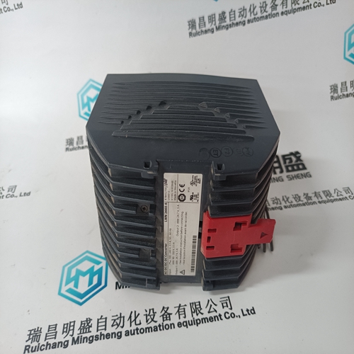
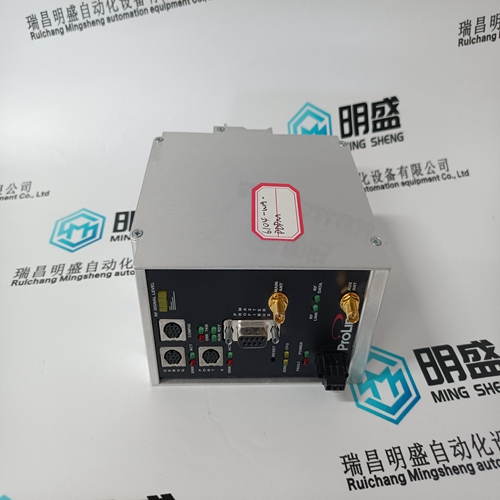
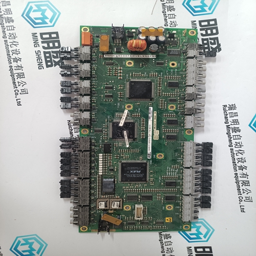
LWN2660-6 Output logic module
- Product ID: LWN2660-6
- Brand: ABB
- Place of origin: The Swiss
- Goods status: new/used
- Delivery date: stock
- The quality assurance period: 365 days
- Phone/WhatsApp/WeChat:+86 15270269218
- Email:stodcdcs@gmail.com
- Tags:LWN2660-6Output logic module
- Get the latest price:Click to consult
The main products
Spare parts spare parts, the DCS control system of PLC system and the robot system spare parts,
Brand advantage: Allen Bradley, BentlyNevada, ABB, Emerson Ovation, Honeywell DCS, Rockwell ICS Triplex, FOXBORO, Schneider PLC, GE Fanuc, Motorola, HIMA, TRICONEX, Prosoft etc. Various kinds of imported industrial parts
Products are widely used in metallurgy, petroleum, glass, aluminum manufacturing, petrochemical industry, coal mine, papermaking, printing, textile printing and dyeing, machinery, electronics, automobile manufacturing, tobacco, plastics machinery, electric power, water conservancy, water treatment/environmental protection, municipal engineering, boiler heating, energy, power transmission and distribution and so on.
LWN2660-6 Output logic module
Reference temperature (RT) A maximum allowable pressure related to the PN number (see 3.2) given in this standard is applicable at the Reference Temperature (RT). RT is defined as the temperature range from -10 °C up to and including 50 °C. Up to and including 50°C all flange types are suitable for the given PN. The flanges may be used for temperatures above 50 °C. For this higher temperature the p/t-rating needs to be calculated. Down to and including -10 °C all materials listed in Table 9 are suitable for a maximum allowable pressure related to the PN number without any further testing than the testing specified in the EN material standard. The materials may be used for lower temperatures. Considerations for prevention of low temperature brittle fracture may be necessary depending on the temperature, the material and heat treatment condition. NOTE The EN product standards (e.g. EN 13445, EN 13480, EN 13458) specify guidance regarding the prevention of low temperature brittle fracture. F.1.2 Application limits and equations For flanges designated in accordance with 4.2 of this European Standard, the maximum allowable pressure PS calculated at temperature shall not exceed a maximum allowable pressure related to the PN number.
Flanges made from steel castings
For flanges made from steel casting (types no. 21, 34) the actual dimension needs to be calculated to comply with the p/t-ratings for steel forging / flat product. The calculation shall also be done under the rules of the component or equipment standard applicable for the component or pressure equipment of which this flange is an integral part (e.g. EN 12516 for valves). All mating dimensions, the neck diameter (N3) and (minimum) flange wall thickness shall be as given in Tables 10 to 21. NOTE For flanges type 21 see footnote a of Table 6 and NOTE 5 of 5.6.1. F.2.7 Rounding of maximum allowable pressure at temperature The results of calculated maximum allowable pressure PS at temperature (according to F2.2-1 respectively F.2.3-1) shall be rounded downwards to the first decimal place (e.g. value of 15,09 bar rounded downwards to 15,0 bar; or 15,19 bar rounded downwards to 15,1 bar).A range of p/t-ratings for a selection of commonly used EN materials is indicated in this annex. These p/t-ratings are prepared to support the user of this European Standard and shall not be understood either as a limitation in p/tratings nor materials. If the user of this European Standard has the need to determine his own p/t-rating for a certain application this can be done under consideration of the basic rules to determine a p/t-rating (see Annex F).
Basics of determination of p/t-ratings (see Annex F)
p/t-ratings are calculated by using the equations F.2.2-1 and F.2.3-2. In compliance with Equation F.2-1, the calculated pressure values do not exceed PN. Strength values for steel forgings, flat steel products and steel castings are taken from EN material standards considering the different range of product thickness. For provisions regarding the reference value for thickness v R see F.2.4. p/t-ratings are calculated by using the strength values of steel forgings depending on different range of product thickness and are verified for flat steel products of the same group. Nominal design stresses are calculated by using the equations as defined in Table F.2.5-1. Interpolation rules as defined in Annex F have been applied. NOTE 1 The graduation of vR depends from the product of material from which a flange is manufactured. For the different methods of fabrication see Table 1 of this European Standard. NOTE 2 For flanges made from steel casting (type 21) see footnote a of Table 6 and definitions stated in F.2.6. NOTE 3 If the flange joint consists of materials with different strength properties (excluding bolts), p/t-ratings need to be chosen in accordance with the lowest strength values. NOTE 4 The p/t-ratings are to be build by a comparison of a material related term (ft;fCR) and the value of 140 MPa to PN. ft;fCR are a function of the material thickness for a given material. To compare the results of F.2.2-1 and F.2.3-1 with the thickness of a flange of this European Standard vR is introduced in this European Standard.
