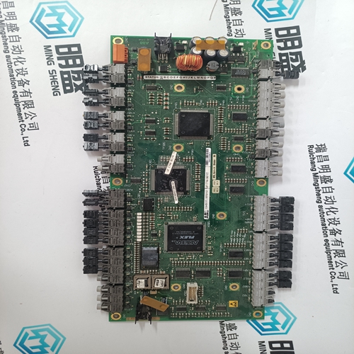
Home > Product > DCS control system > UFC760BE41 3BHE004573R0041 pulse output card
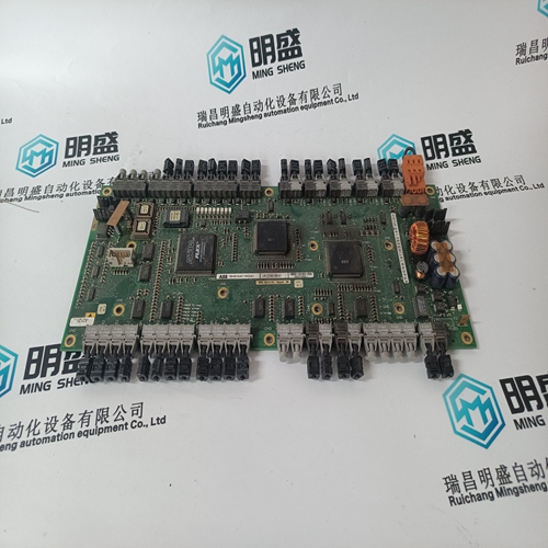
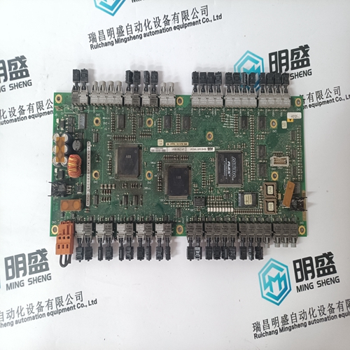
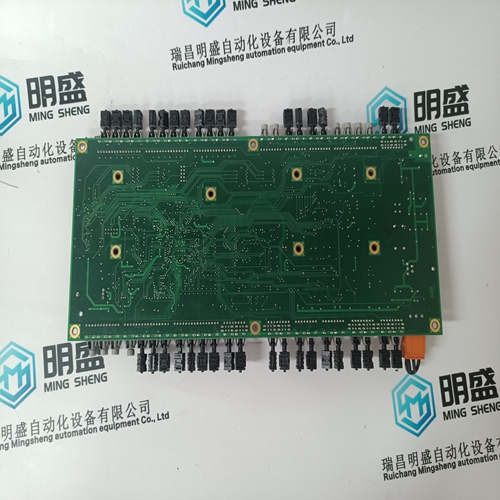
UFC760BE41 3BHE004573R0041 pulse output card
- Product ID: UFC760BE41 3BHE004573R0041
- Brand: ABB
- Place of origin: The Swiss
- Goods status: new/used
- Delivery date: stock
- The quality assurance period: 365 days
- Phone/WhatsApp/WeChat:+86 15270269218
- Email:stodcdcs@gmail.com
- Tags:UFC760BE41 3BHE004573R0041pulse output card
- Get the latest price:Click to consult
The main products
Spare parts spare parts, the DCS control system of PLC system and the robot system spare parts,
Brand advantage: Allen Bradley, BentlyNevada, ABB, Emerson Ovation, Honeywell DCS, Rockwell ICS Triplex, FOXBORO, Schneider PLC, GE Fanuc, Motorola, HIMA, TRICONEX, Prosoft etc. Various kinds of imported industrial parts
Products are widely used in metallurgy, petroleum, glass, aluminum manufacturing, petrochemical industry, coal mine, papermaking, printing, textile printing and dyeing, machinery, electronics, automobile manufacturing, tobacco, plastics machinery, electric power, water conservancy, water treatment/environmental protection, municipal engineering, boiler heating, energy, power transmission and distribution and so on.
UFC760BE41 3BHE004573R0041 pulse output card
Guaranteed long service life: ESG
The multi-colour and multi-format labels have a strong
adhesive layer to ensure the best possible adhesion to the
underlying surface. Double laminated polyester makes the
basic material very thin and yet extremely tear-resistant.
Your benefits with MultiMark
• “Different materials for various requirements“
• Can be used with equipment from many manufacturers
• Device markers with a familiar design
Setup and operation of the device/equipment/system in question must only be performed using this documentation. Commissioning and operation of a device/ system may only be performed by qualified personnel. Qualified personnel as referred to in the safety instructions in this documentation are persons authorized to start up, ground, and label devices, systems, and circuits in accordance with the relevant safety standards. This Configuration Manual provides all of the detailed information required to use and handle SIMODRIVE components. Should you wish for additional information or should exceptional problems arise that are not addressed in sufficient detail in this manual, you can request the required information from your local Siemens office. The Configuration Manual describes a modular drive system. It is permissible to use the constellations and general versions described here. All other combinations must be separately and individually released by Siemens.
Information for using this Manual
The following should be observed when using this manual: 1. Help: The following help is available for the reader: Complete table of contents Header line (as orientation): the main chapter is in the upper header line the sub–chapter is in the lower header line Appendix with – Abbreviations and List of References – Index If you require information regarding a specific term, then look for this in the Appendix under the Chapter ”Index”. The Chapter number as well as the page number is specified where information on this term can be found. 2. Edition of the documentation: The history of the document editions is summarized in the printing history. The header of the document indicates the current edition (12/2006).Reader’s note Only the digital components for a SIMODRIVE group with High Performance/ High Standard and 611 universal modules are described in Edition A10.04 and higher. Please refer to the overview in Chapter 4.1 regarding from which software releases, use is possible. The descriptions for the relevant controls in the Configuration Manual, Edition 02.03, still remain valid for the analog components that have been discontinued (not for new configurations)!
Safety information
This documentation contains information that must be observed to ensure your personal safety and to prevent material damage. The instructions for your personal safety are marked by a warning triangle. Instructions relating solely to material damage are not marked by a warning triangle. The warnings appear in decreasing order of risk as given below.
As a result of the high switching frequencies, capacitances (parasitic and integrated) with respect to ground may cause high leakage currents. This is the reason that a permanent PE connection is required at the control cabinet and at the line filter! Measures according to EN 50178/94 Part 5.3.2.1 must be implemented, e.g. 1. Copper protective conductor with a minimum cross–section of 10 mm2 should be connected, or 2. A second conductor should be connected in parallel with the protective conductor through separate terminals. This conductor must also fully meet the requirements for PE conductors according to IEC 364–5–543.
