Home > Product > Gas turbine system > D20-PS LFDSC143-4000 Gas turbine module
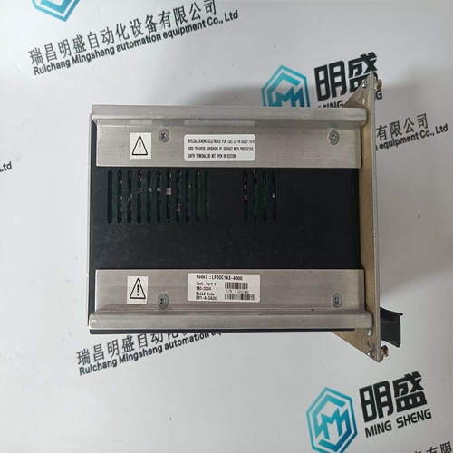
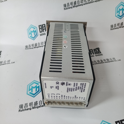
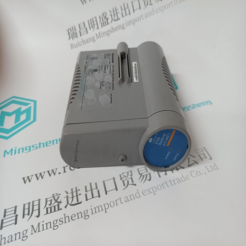
D20-PS LFDSC143-4000 Gas turbine module
- Product ID: D20-PS LFDSC143-4000
- Brand: GE
- Place of origin: the United States
- Goods status: new/used
- Delivery date: stock
- The quality assurance period: 365 days
- Phone/WhatsApp/WeChat:+86 15270269218
- Email:stodcdcs@gmail.com
- Tags:D20-PS LFDSC143-4000Gas turbine module
- Get the latest price:Click to consult
The main products
Spare parts spare parts, the DCS control system of PLC system and the robot system spare parts,
Brand advantage: Allen Bradley, BentlyNevada, ABB, Emerson Ovation, Honeywell DCS, Rockwell ICS Triplex, FOXBORO, Schneider PLC, GE Fanuc, Motorola, HIMA, TRICONEX, Prosoft etc. Various kinds of imported industrial parts
Products are widely used in metallurgy, petroleum, glass, aluminum manufacturing, petrochemical industry, coal mine, papermaking, printing, textile printing and dyeing, machinery, electronics, automobile manufacturing, tobacco, plastics machinery, electric power, water conservancy, water treatment/environmental protection, municipal engineering, boiler heating, energy, power transmission and distribution and so on.
D20-PS LFDSC143-4000 Gas turbine module
Gating and electronic points used to determine the load limits of the power supply. It is not possible to specify the power rating of an individual voltage source as several power supplies are coupled with one another. If the number of gating or electronic points is exceeded, an additional power supply must be used – the ”monitoring module”. When determining the gating (AP) and electronic points (EP) refer to Chapter 6.6. When calculating the power supply rating, refer to Chapter LEERER MERKER. Every infeed module has a maximum value that applies when expanding the DC link capacitors. It must be ensured that the DC link capacitance in the selected drive group is not exceeded (refer to Table 1-1). The sum (total) of the DC link capacitances (refer to Chapter LEERER MERKER, Table 1-4) of all modules must be less than or equal to the charge limit corresponding to the following table of the infeed modules:The rated motor current may not exceed the rated output current of the power modules. The maximum motor current must always be less than the maximum converter current.
Braking operation
With the UI modules, only deceleration with pulsed resistors is possible. With I/R modules, a regenerative feedback of excess energy to the supply system also occurs. For required braking operations in the event of a power failure, the braking module and pulsed resistors are also needed. The regenerative feedback power is dependent on the available energy to be braked in the system: The mass Speed/velocity Braking ramps/braking time Efficiencies The sum of PS FD and PS MSD should be calculated from all of the feed axes and main spindles that are simultaneously operated. This calculated power must be less than the peak power of the regenerative feedback module.
A SIMODRIVE drive group has a modular configuration comprising line filter, commutating reactor, line supply infeed module, drive modules as well as, when required: monitoring, pulsed resistor and capacitor module(s). Satisfactory operation is ensured only in conjunction with the components that are described in this Configuration Manual or published in the Catalog NC60 (Internet Mall) and with adherence to the required boundary/application conditions. Failure to observe this along with improper use and application conditions can void your certifications, conformity declarations or warranty claims. In order to avoid contamination, the modules should be installed in a control cabinet with degree of protection IP 54. Modules can also be arranged in several tiers one above the other or next to one another.
Checking the permissible power supply rating
The infeed or monitoring module used offers a basic equipping of the electronic (EP values) and control power supply (AP values). The following table is used to determine the power supply requirement of a drive line–up. The number of modules used should be entered. The product from ”Evaluation factor individual module” and ”Number of modules” should be formed. An (additional) monitoring module must be provided if one of these values is exceeded. The following tables should be used again for the module line–up, supplied from the monitoring module. The monitoring module must be located to the left in front of the modules to be monitored.
According to IEC 61800–5–1, a PDS (Power Drive System) with leakage currents over 3.6 mA requires a secure ground connection (e.g. at least 10 mm2 Cu or multiple connection) or an automatic shutdown in case of a ground connection fault. The housings of the SIMODRIVE 611 converter system modules are enclosed and EMC–compatible as specified in EN 60529 (IEC 60529). The electrical system is designed to comply with EN 50178 (VDE 0160) and EN 60204, and an EC declaration of conformity is available. The connections in the module group, motor cables, encoder lines and bus lines must be made using preassembled MOTION–CONNECT lines (see Catalog NC 60).