Home > Product > Servo control system > DANAHER S20660-SRS drive module
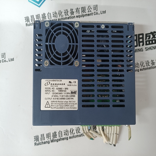
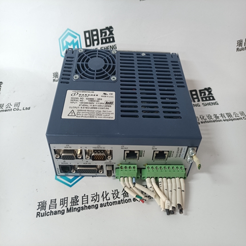
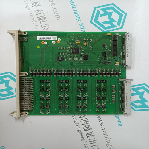
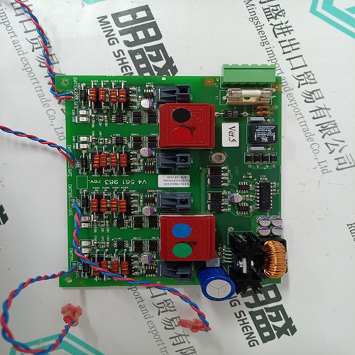
DANAHER S20660-SRS drive module
- Product ID: S20660-SRS
- Brand: DANAHER
- Place of origin: the United States
- Goods status: new/used
- Delivery date: stock
- The quality assurance period: 365 days
- Phone/WhatsApp/WeChat:+86 15270269218
- Email:stodcdcs@gmail.com
- Tags:DANAHERS20660-SRSdrive module
- Get the latest price:Click to consult
The main products
Spare parts spare parts, the DCS control system of PLC system and the robot system spare parts,
Brand advantage: Allen Bradley, BentlyNevada, ABB, Emerson Ovation, Honeywell DCS, Rockwell ICS Triplex, FOXBORO, Schneider PLC, GE Fanuc, Motorola, HIMA, TRICONEX, Prosoft etc. Various kinds of imported industrial parts
Products are widely used in metallurgy, petroleum, glass, aluminum manufacturing, petrochemical industry, coal mine, papermaking, printing, textile printing and dyeing, machinery, electronics, automobile manufacturing, tobacco, plastics machinery, electric power, water conservancy, water treatment/environmental protection, municipal engineering, boiler heating, energy, power transmission and distribution and so on.
DANAHER S20660-SRS drive module
The modules must be arranged in a particular layout. The following criteria must be taken into account: Function of the module Cross–section of the DC link busbar The I/R or UI module is always located to the left of the module group at the beginning. The power modules (PM) are located to the right next to the I/R or UI modules (refer to Fig. 2-1).
Due to the limited conductivity of the DC link busbars of the modules with module width 150 mm, the DC link power PZK of these modules must not exceed 55 kW. Larger DC link busbars must be used if this restriction cannot be complied with (refer to Fig. 2-2 and 2-3). The DC link power PZK of the subsequent modules is calculated according to the engineering rule specified in Chapter 1.3. The larger DC link busbars can be ordered as a set with Order No. [MLFB] 6SN1161–1AA02–6AA0. The set includes reinforced DC link busbars for module widths 50 mm, 100 mm and 150 mm. The standard DC link brackets between the modules may not be changed, even when strengthened DC link busbars are used.
Arrangement of the modules and their mounting
2-44 © Siemens AG 2013 All Rights Reserved SIMODRIVE 611 Configuration Manual (PJU) – 06/2013 Edition Subject to certain conditions, several pulsed resistor modules can be connected in parallel (refer to Chapter LEERER MERKER, Table 1-4). The drive bus length may not exceed 11 m. For more than six modules, control units, round cables must be used (refer to Chapter 2.1.2). The equipment bus cable that is looped–through a drive group at an infeed or monitoring module may not exceed 2.1 m from the supply connection point. For a two–tier configuration, two equipment bus branches are possible, each with a maximum length of 2.1 m from the branch point at the supply connection point. The permitted cable lengths depend on the used line filters, refer to the line filters in Section 7.4. Reader’s note For cable lengths for SIMODRIVE POSMO SI/CD/CA, refer to Reference: /POS3/ User Manual SIMODRIVE POSMO SI/CD/CA The electronics power supply between the individual modules is established using the equipment bus cable (refer to Fig. 2-1). The equipment bus cable is included in the scope of supply of the power module.
Mounting and installing the modules
When mounting and installing the SIMODRIVE modules on the rear cabinet panel, proceed in the following sequence: 1. Screw–in the retaining screws up to a clearance of approx. 4 mm from the surface of the mounting panel. 2. Locate the modules in the screws and then tighten the screws with 6 Nm. 3. Locate the DC link connecting bar in the adjacent module under the screws provided and tighten these screws with 1.8 Nm –0/+30%. The DC link covers must only be installed with the power turned off. Check the spring elements for exact positioning prior to installation. Covers with warped spring elements must be replaced.
Any conductive dirt/pollution can result in the safe electrical separation being lost and can therefore result in hazards to personnel (electric shock).
