Home > Product > DCS control system > REF542PLUS 1VCF752000 Industrial control host
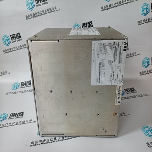
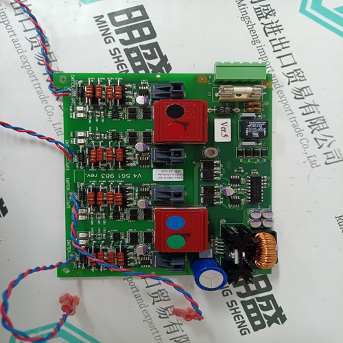
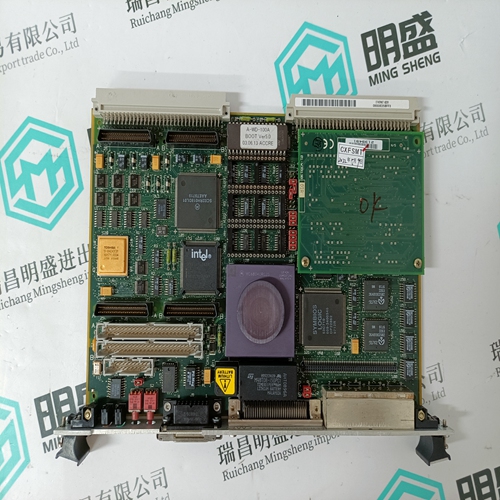
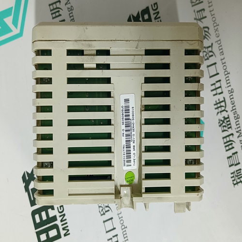
REF542PLUS 1VCF752000 Industrial control host
- Product ID: REF542PLUS 1VCF752000
- Brand: ABB
- Place of origin: The Swiss
- Goods status: new/used
- Delivery date: stock
- The quality assurance period: 365 days
- Phone/WhatsApp/WeChat:+86 15270269218
- Email:stodcdcs@gmail.com
- Tags:REF542PLUS 1VCF752000Industrial control host
- Get the latest price:Click to consult
The main products
Spare parts spare parts, the DCS control system of PLC system and the robot system spare parts,
Brand advantage: Allen Bradley, BentlyNevada, ABB, Emerson Ovation, Honeywell DCS, Rockwell ICS Triplex, FOXBORO, Schneider PLC, GE Fanuc, Motorola, HIMA, TRICONEX, Prosoft etc. Various kinds of imported industrial parts
Products are widely used in metallurgy, petroleum, glass, aluminum manufacturing, petrochemical industry, coal mine, papermaking, printing, textile printing and dyeing, machinery, electronics, automobile manufacturing, tobacco, plastics machinery, electric power, water conservancy, water treatment/environmental protection, municipal engineering, boiler heating, energy, power transmission and distribution and so on.
REF542PLUS 1VCF752000 Industrial control host
The technical data of the power modules is specified in Table 5-1 for the 1–axis version and in Table 5-2 for the 2–axis version. The specified values are valid for: The specified rated frequency (inverter pulse frequency) Maximum ambient temperature of 40 °C Installation altitude<1000 m above sea level Derating must be applied for conditions that deviate from those specified above. The power modules do not have any overload protection, but only a current acquisition without its own processing. The overload protection is realized in the SIMODRIVE 611 control unit. Also refer to the definition of the load duty cycles (Fig. 5-2 to 5-5) FD mode – In Continuous nominal current, rated current – Imax Peak current Operating modes, MSD–IM and MSD–SRM – In Continuous nominal current, rated current – IS6–40% Current for maximum of 4 min. for the S6 load duty cycle – Imax Peak current – Imin Minimum motor current – nFS Speed at the start of field weakening
for induction motors
– The no–load current of the motor (I0Mot) must be less than the rated current of the power module (according to Table 5-1). – On the basis of the actual current value resolution, the lowest occurring no–load current of the motor must satisfy the following condition: nmax nFS I0Mot Imin (Imin according to Table 5-1) for synchronous motors: A ratio of Imax_powersection/I0_100K (motor) 5 should not be exceeded for synchronous motors. Appropriate values are specified in Table 5-1 and 5-2 to dimension the cabinet cooling. These are defined as follows: PVtot Total power loss dissipated by the module PVext Power loss that can be dissipated externally or using hose cooling PVint Power loss that cannot be dissipated using hose cooling or external cooling (this power loss remains in the control cabinet) For components with internal cooling, the complete dissipated power loss remains in the control cabinet.
Current reduction/derating
The current has to be reduced if one or more of the following limitations/secondary conditions apply: Selected inverter pulse frequency fT > reference frequency f0 Installation altitude>1000 m above sea level Ambient temperature TU > 40 °C Notice The currents must be reduced for In, Is6 and Imax in the same way. All of the relevant limitations/secondary conditions must be taken into account with an appropriate reduction factor (refer to the calculation example, Chapter 5.4.4). 5.4.1 Pulse frequency power modules The current should be reduced from the reference frequency f0 onwards according to the following rule: XT = 100% – (100% – XL) (f – f0) 8 kHz – f0 The pulse frequency of the power modules (inverters) must be at least factor 5 for the maximum motor frequency! f0 Pulse frequency reference frequency in accordance with the technical data f set inverter pulse frequency TU ambient temperature XL power module-specific derating factor for the inverter pulse frequency XT derating factor for the inverter pulse frequency XH derating factor for the ambient temperature XTU derating factor for the installation altitude as a %

